
Electroluminescence display device

a display device and electroluminescent technology, applied in the direction of basic electric elements, semiconductor devices, electrical equipment, etc., can solve the problems of more of an issue, image quality may be deteriorated, dark defects, etc., to minimize the electrical resistance of the cathode and improve the effect of an aging process

Pending Publication Date: 2022-05-05
LG DISPLAY CO LTD
View PDF0 Cites 0 Cited by
  • Summary
  • Abstract
  • Description
  • Claims
  • Application Information

AI Technical Summary

Benefits of technology

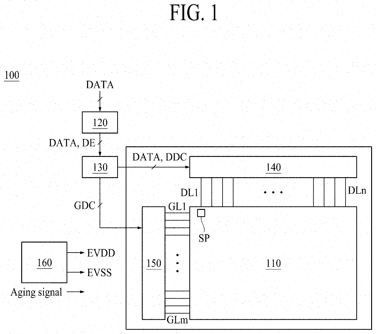
The present invention aims to improve the efficiency of removing defects caused by short circuits between the anode and cathode in an electroluminescence display device. It also aims to minimize the electrical resistance of the cathode.

Problems solved by technology

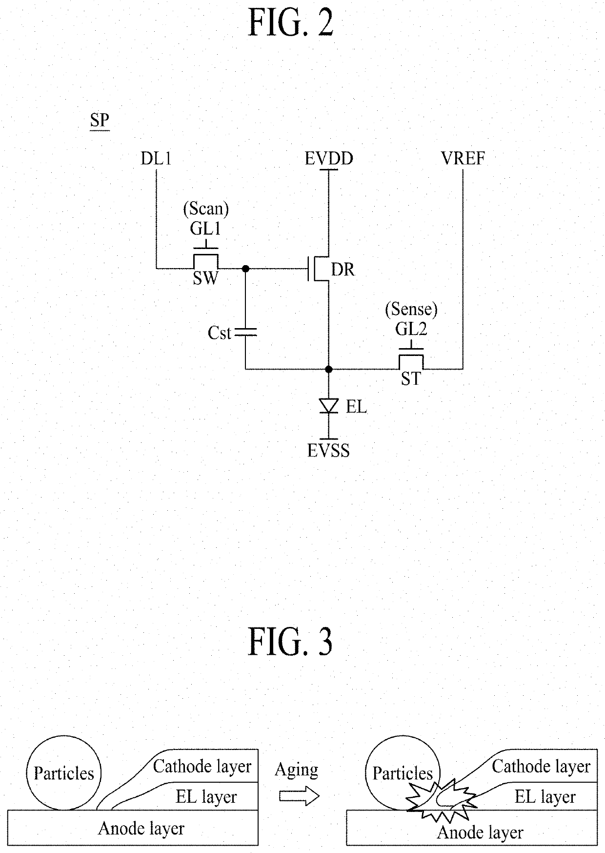
The manufacturing process of forming the organic light emitting element may cause a short due to particles generated between an anode and a cathode, thereby causing a dark defect.
This problem may be more of an issue in a top emission display device.
For this reason, a problem may occur in that image quality may be deteriorated.

Method used


Image

  • Electroluminescence display device
  • Electroluminescence display device
  • Electroluminescence display device

Examples


Embodiment Construction

[0031]Reference will now be made in detail to embodiments of the present disclosure, examples of which are illustrated in the accompanying drawings.

[0032]Advantages and features of the present disclosure, and implementation methods thereof will be clarified through following example embodiments described with reference to the accompanying drawings. The present disclosure may, however, be embodied in different forms and should not be construed as limited to the example embodiments set forth herein. Rather, these example embodiments are provided so that this disclosure may be sufficiently thorough and complete to assist those skilled in the art to fully understand the scope of the present disclosure. Further, the protected scope of the present disclosure is defined by claims and their equivalents.

[0033]The shapes, sizes, ratios, angles, numbers, and the like, which are illustrated in the drawings in order to describe various example embodiments of the present disclosure, are merely gi...


PUM


Abstract

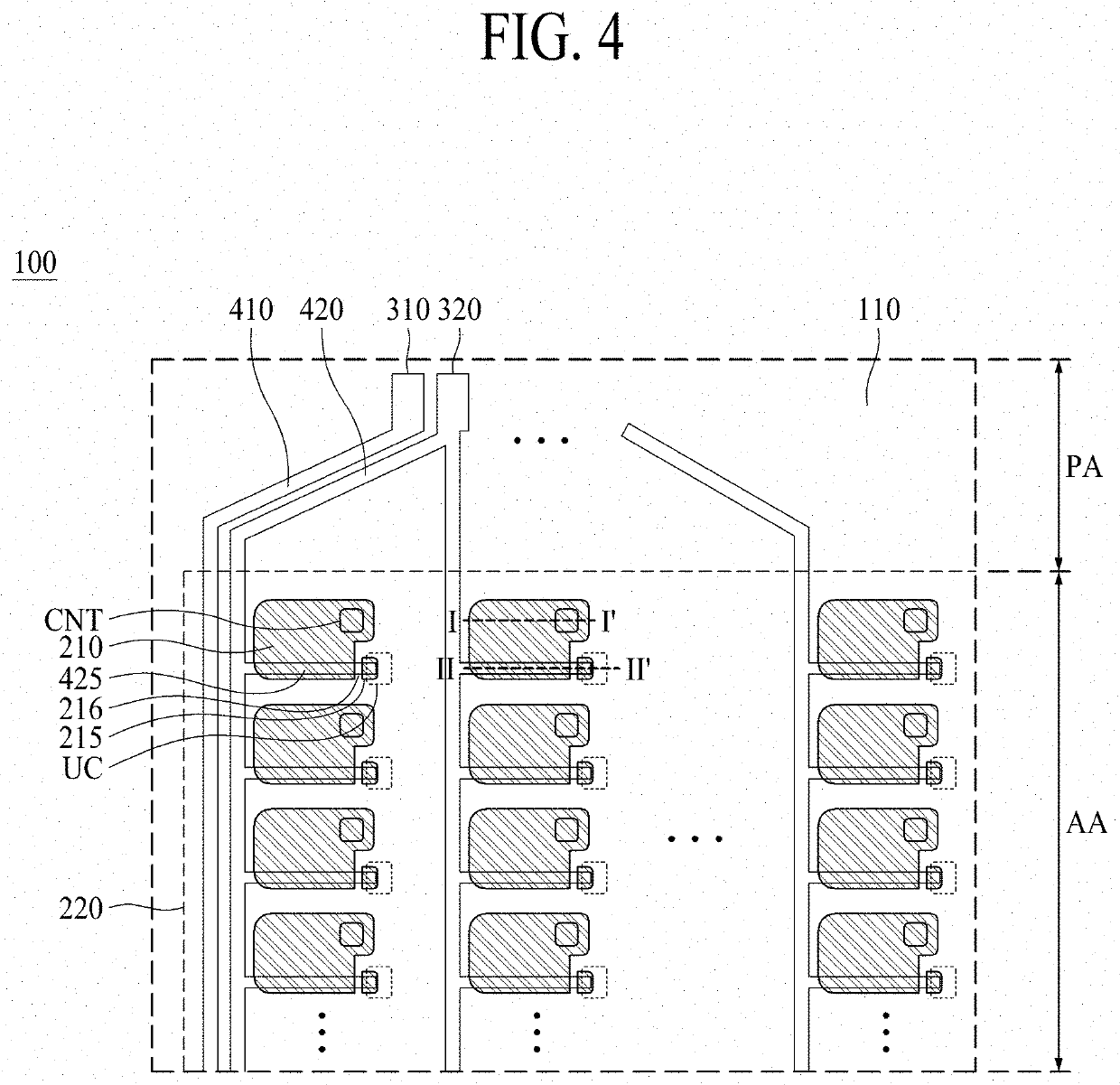
An electroluminescence display device comprises a substrate including a pixel area having a light emitting portion and a non-light emitting portion adjacent to the light emitting portion; a first electrode in the light emitting portion of the pixel area; an auxiliary electrode in the non-light emitting portion of the pixel area and spaced apart from the first electrode; a light emitting layer on the first electrode; a second electrode on the light emitting layer in the pixel area and connected to the light emitting layer; and an auxiliary power electrode below the first electrode and electrically connected with the auxiliary electrode.

Description

CROSS-REFERENCE TO RELATED APPLICATIONS[0001]This application claims the benefit of and priority to Korean Patent Application No. 10-2020-0146500 filed on Nov. 5, 2020, which is hereby incorporated by reference as if fully set forth herein.BACKGROUND1. Technical Field[0002]The present disclosure relates to an electroluminescence display device.2. Discussion of the Related Art[0003]With the advancement of the information age, the demand for a display device for displaying an image has increased in various forms. Therefore, various types of display devices, such as a liquid crystal display (LCD) device, a field emission display (FED) device, a plasma display panel (PDP) device, and an electroluminescence display device, have been recently used.[0004]Among such display devices, the electroluminescence display device is classified into an inorganic light emitting display device and an organic light emitting display device, depending on a material of a light emitting layer. The organic l...

Claims


Application Information

Patent Timeline
IPC IPC(8): H01L27/32H01L51/52
CPCH01L27/3276H01L51/5228H01L51/5212H01L51/5218H10K59/131H10K59/80522H10K59/80518H10K59/80516H10K71/831H10K50/814H10K50/818H10K50/824
Inventor KIM, MOONSOOLEE, SUNGBAIKIM, SUHYEON
Owner LG DISPLAY CO LTD
Learn More