Cable Stripping Device

a cable stripping and cable technology, applied in the field of high-voltage electrical power transportation cables or, can solve the problems of proving to be a relatively painstaking task, affecting reducing the safety of operators' tools, so as to achieve the effect of convenient handling

Active Publication Date: 2022-05-05
SILEC CABLE
View PDF0 Cites 0 Cited by
  • Summary
  • Abstract
  • Description
  • Claims
  • Application Information

AI Technical Summary

Benefits of technology

[0024]Optionally, the device comprises at least on...

Problems solved by technology

This then proves to be a relatively painstaking task especially since the tool with which the operators strip the cables is fitted with s...

Method used


Image

  • Cable Stripping Device
  • Cable Stripping Device

Examples


Embodiment Construction

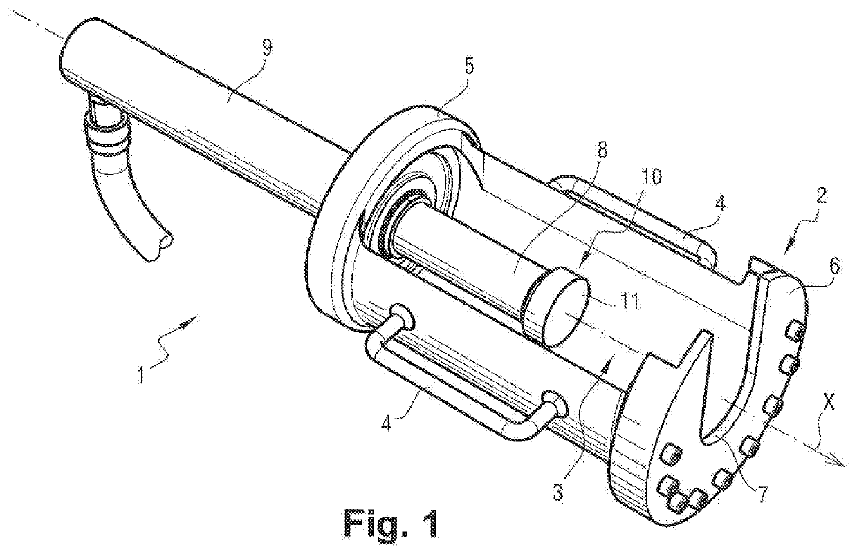
[0029]With reference to FIG. 1, the device according to one particular embodiment of the invention, denoted overall as 1, comprises an extraction chamber 2 extending longitudinally along a first axis X.

[0030]The extraction chamber 2 comprises a central body 3.

[0031]The central body 3 is generally configured as a right cylinder, with its directrix straight line coinciding with the first axis X. According to one particular embodiment, the central body 3 is also open over its entire length (considered along the first axis X) but over just an angular sector of its cylindrical surface. Typically, said angular sector is comprised between 90 and 200 degrees. As a preference, the angular sector represents substantially 180 degrees so that the cylindrical surface of the central body 3 is configured as a half-cylinder.

[0032]The extraction chamber 2 here has no cover for removably closing said central body 3.

[0033]As a preference, the device 1 comprises at least one handle to make the extracti...


PUM


Abstract

The invention concerns a cable stripping device, the device comprising at least:—an extraction chamber (2) of which a distal end is closed by a flange (7) comprising a groove (7), —a pusher (8) movably mounted in the extraction chamber between a rest position in which the pusher extends at a proximal end of the chamber and a deployed position, the pusher being intended to push on the cable in order to press it against the groove of the flange.

Description

[0001]The invention relates to a device for stripping a cable.BACKGROUND OF THE INVENTION[0002]In the field of high-voltage electrical power transporting cables or medium-voltage power transporting cables, it is commonplace for the cables to be delivered to site unfinished, which means to say without cable accessories.[0003]It is therefore on site that the operators prepare the two ends of each cable, either in order to join two cables together or in order to add by way of accessory a cable termination such as a silicone sleeve termination.[0004]In order to do that, the operators have to use a tool to strip the ends of the cables so as to remove the layers surrounding the central electrical conductor (which is sometimes stranded) in order to prepare it for joining to another cable and / or a cable termination accessory. This then proves to be a relatively painstaking task especially since the tool with which the operators strip the cables is fitted with somewhat unsuitable cutters.[00...

Claims


Application Information

Patent Timeline
IPC IPC(8): H01R43/28H02G1/12
CPCH01R43/28H02G1/1214H02G1/1258
Inventor TOP, ABDOU-KARIMLAGNEAU, DIDIERCASUC, CHRISTOPHE
Owner SILEC CABLE
Why Eureka
Try Eureka