
Electrically isolating baffle for horticulture grow light

a technology for horticulture and grow lights, applied in semiconductor devices, light sources, light sources, etc., can solve the problems of shortening the life of grow lights, inefficient operation, and uncomfortable for workers, and achieve the effect of reducing the cooling efficiency of active cooling devices and safe and efficient cooling of grow lights

Active Publication Date: 2022-05-19
CABATECH LLC
View PDF0 Cites 0 Cited by
  • Summary
  • Abstract
  • Description
  • Claims
  • Application Information

AI Technical Summary

Benefits of technology

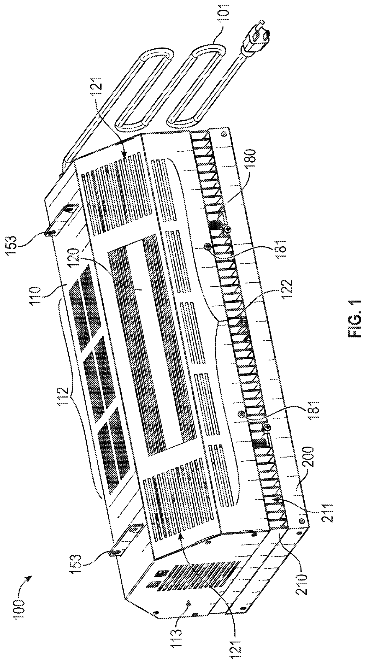
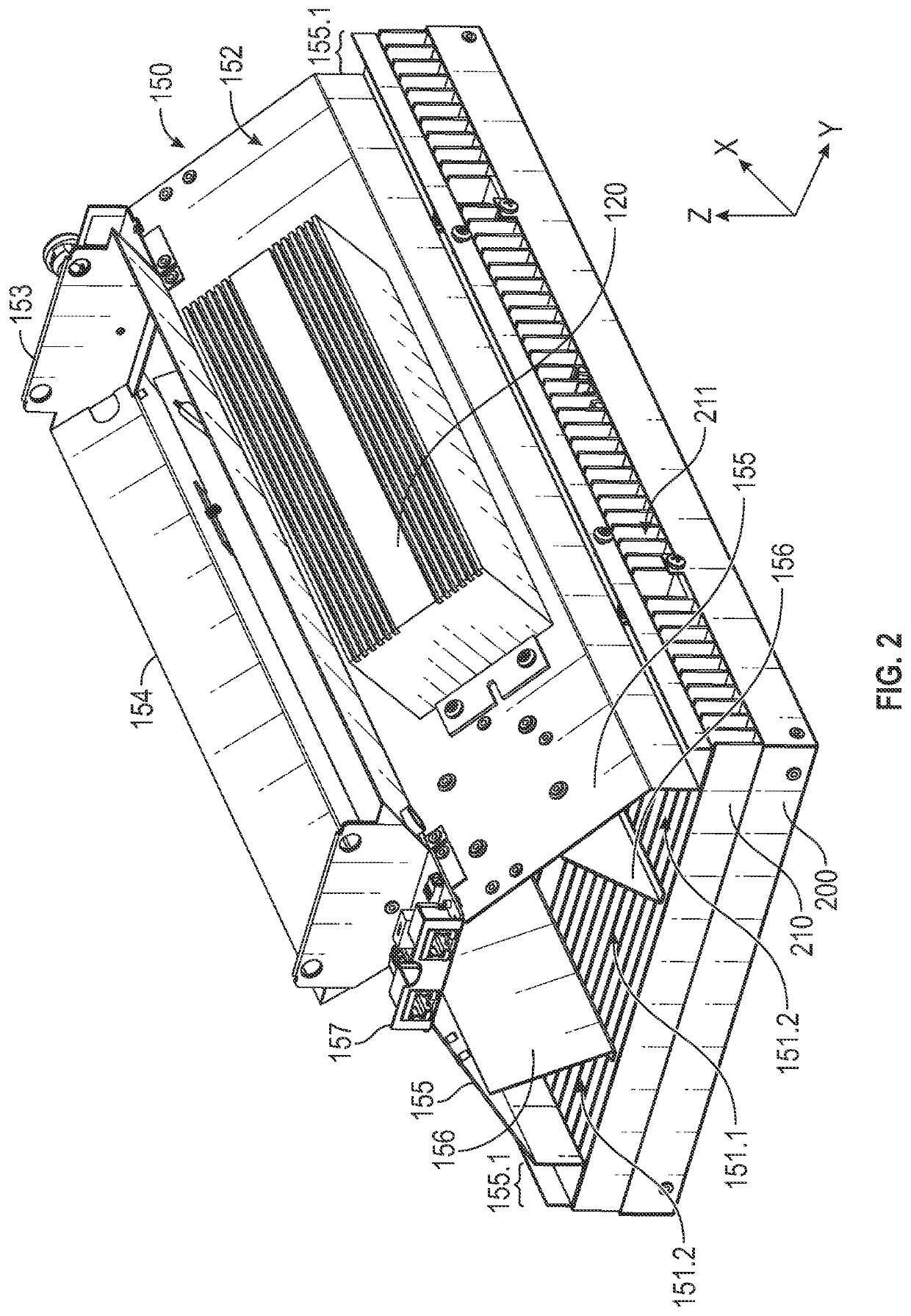
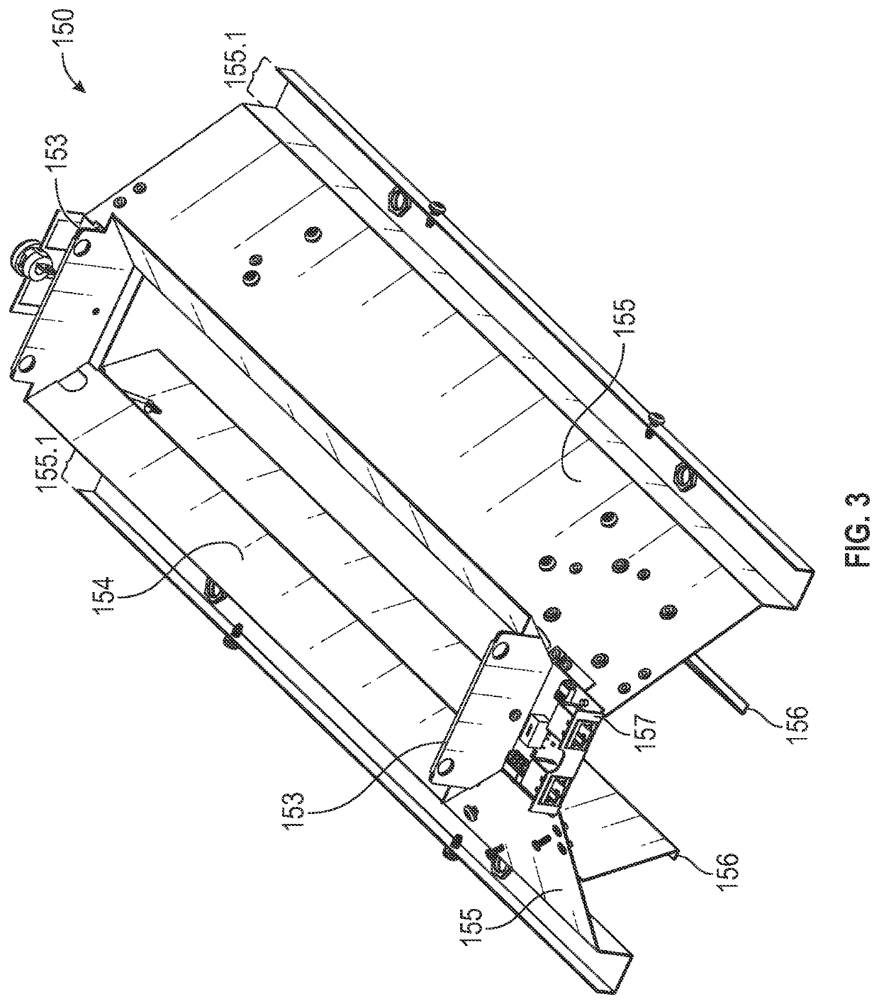
This patent describes a way to cool grow lights used in horticulture, while ensuring the safety of workers. A baffle is added to the grow light, which has separate airflow sections to prevent the formation of a boundary layer of air that would reduce cooling efficiency. The baffle also isolates moving parts of the cooling system from drivers and electrical wiring, allowing for more venting to cool additional components without affecting the cooling of the grow light. The technical effect is better and safer cooling of the grow light using an efficient and reliable system.

Problems solved by technology

But such fans and HVAC systems only incidentally cool the grow lights, which can result in the grow lights overheating, can shorten their lifespan, or cause them to operate inefficiently.
Further, in colder environments or when growing cold-weather tolerate crops, such fans may be unnecessary or may be even overchill a building, making it uncomfortable for workers.
However, simply attaching (or mounting) a fan onto a grow light is not a simple matter.
For example, the moving parts of the fan in close proximity to electrical wires powering the light source poses an electrocution risk to workers by, for example, frayed wires or the like.
The different active airflow sections prevent or substantially prevent the formation of boundary layer air that would reduce the cooling efficiency of the active cooling device.

Method used


Image

  • Electrically isolating baffle for horticulture grow light
  • Electrically isolating baffle for horticulture grow light
  • Electrically isolating baffle for horticulture grow light

Examples


Embodiment Construction

[0037]Hereinafter, example embodiments of the present disclosure will be described, in more detail, with reference to the accompanying drawings. The present disclosure, however, may be embodied in various different forms and should not be construed as being limited to only the embodiments illustrated herein. Rather, these embodiments are provided as examples so that this disclosure will be thorough and complete and will fully convey the aspects and features of the present disclosure to those skilled in the art. Accordingly, processes, elements, and techniques that are not necessary to those having ordinary skill in the art for a complete understanding of the aspects and features of the present disclosure may not be described. Unless otherwise noted, like reference numerals denote like elements throughout the attached drawings and the written description, and thus, descriptions thereof may not be repeated.

[0038]It will be understood that, although the terms “first,”“second,”“third,” ...


PUM


Abstract

A horticulture grow light includes: an emitter array; a heatsink on one side of the emitter array; a driver electrically connected to the emitter array; and an electrically isolating baffle connected to the heatsink. The baffle includes: an air funnel; a plurality of driver panels respectively connected at opposite sides of the air funnel and extending toward the heatsink; and a plurality of support panels respectively connected to the driver panels and extending toward the heatsink. A first active airflow section is formed between inner surfaces of the driver panels and inner surfaces of the support panels, and second active airflow sections are respectively formed on either side of the first active airflow section and between the inner surfaces of the driver panels and outer surfaces of the support panels.

Description

CROSS-REFERENCE TO RELATED APPLICATIONS[0001]The present application claims priority to and the benefit of U.S. Provisional Patent Application Ser. No. 63 / 024,879, filed on May 14, 2020, in the United States Patent and Trademark Office, the entire content of which is incorporated herein by reference.[0002]The present application is related to International Patent Application No. PCT / US2016 / 054522, filed Sep. 29, 2017, issued as U.S. Pat. Nos. 9,820,447, 10,159,198, and 10,785,921, the contents of each of which are incorporated herein by reference in their entirety.BACKGROUND1. Field[0003]Aspects of embodiments of the present disclosure are related to an electrically isolating baffle for a horticulture grow light, a horticulture grow light including the electrically isolating baffle, and an air direction system for a horticulture grow light.2. Related Art[0004]As climate change increasingly reduces or relocates arable land while the need for food production continues to increase, the...

Claims


Application Information

Patent Timeline
Patent Type & Authority Applications(United States)
IPC IPC(8): A01G9/24F21V29/76F21V23/00F21V29/67
CPCA01G9/249F21V29/76F21Y2105/16F21V29/67F21V23/002F21V29/763F21Y2115/10F21V23/008
Inventor VILGIATE, ANTHONY WENDELL
Owner CABATECH LLC
Learn More