
Dual-motor differential drive system

a technology of differential drive and gearbox, which is applied in the direction of electric propulsion mounting, gearbox, transportation and packaging, etc., can solve the problems of increasing the manufacturing cost of the drive system, increasing the frictional work consumption between the gears, and increasing the use of the gearbox, so as to reduce heat generation and power consumption

Active Publication Date: 2022-05-19
YANG YING CHUNG +1
View PDF0 Cites 0 Cited by
  • Summary
  • Abstract
  • Description
  • Claims
  • Application Information

AI Technical Summary

Benefits of technology

The patent describes a drive system that connects two motors through differential wheels, which prevents them from interfering with each other during operation. As a result, the system can combine two motors with different speeds and powers to reduce heat generation and power consumption. The system also eliminates the need for a gearbox, reducing manufacturing costs and power consumption. Overall, this system produces more power and reduces the risk of overheating compared to a single motor.

Problems solved by technology

With the increase in power demand, the electric control system has to use high-power components, causing the manufacturing cost of the drive system to increase.
In addition, the usage of the gearbox increases the complexity of the drive mechanism and also increases the frictional work consumption between the gears.
The existing single-motor drive system requires the usage of a water cooling device, which leads to high cost and high power consumption in the single-motor drive system.
However, the existing dual-motor drive system requires the usage of two driving motors with similar output performance, or respectively adjusts the power ratio between the two motors to prevent the dual motors from restricting each other and limiting their output performance.
If a ratchet wheel or a variable speed gear set is used to match the rotational speed and torque of the dual motors, it also leads to high cost and high power consumption.

Method used


Image

  • Dual-motor differential drive system
  • Dual-motor differential drive system
  • Dual-motor differential drive system

Examples


Embodiment Construction

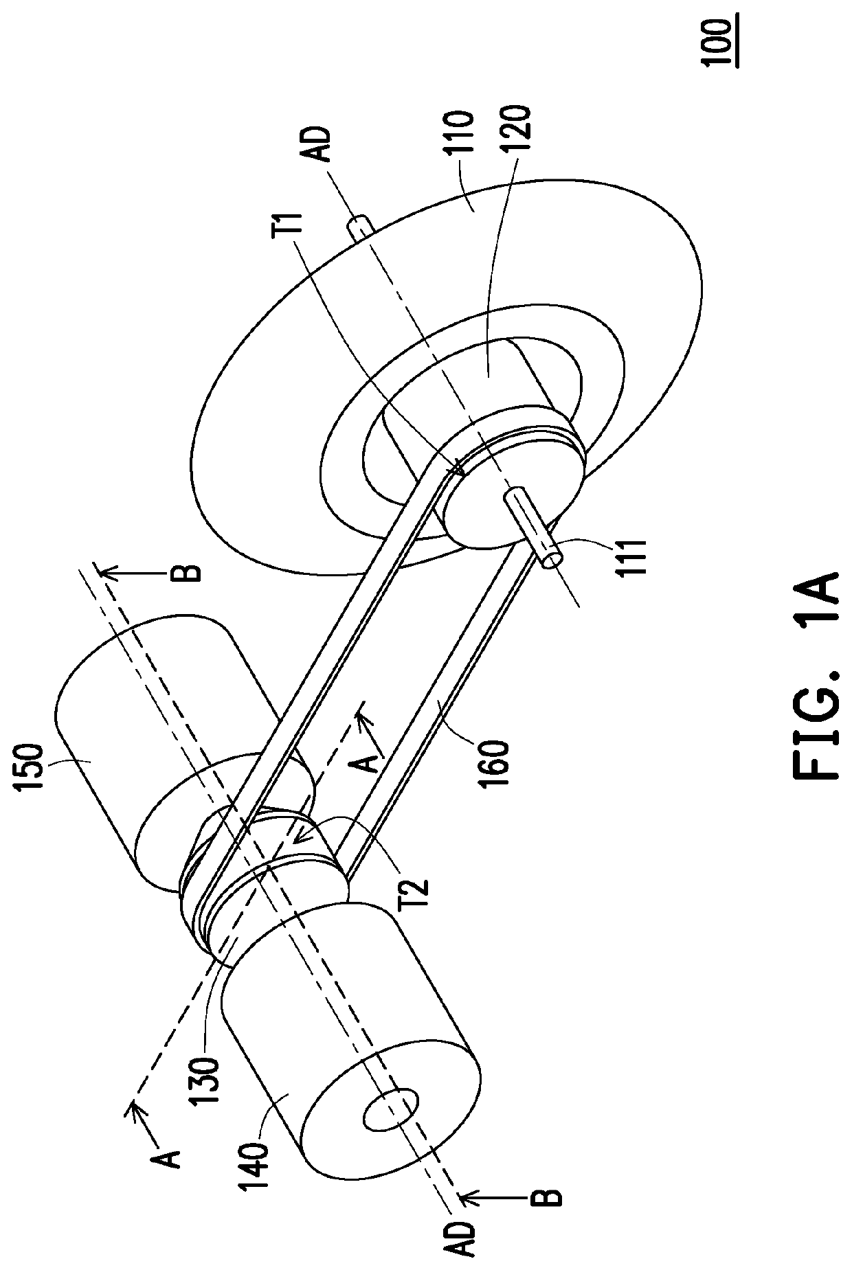
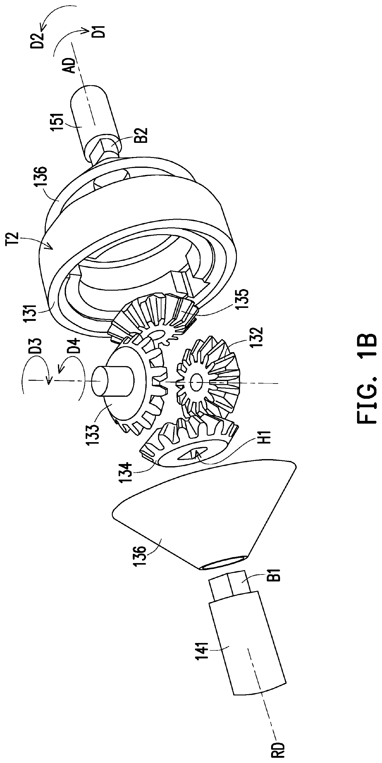
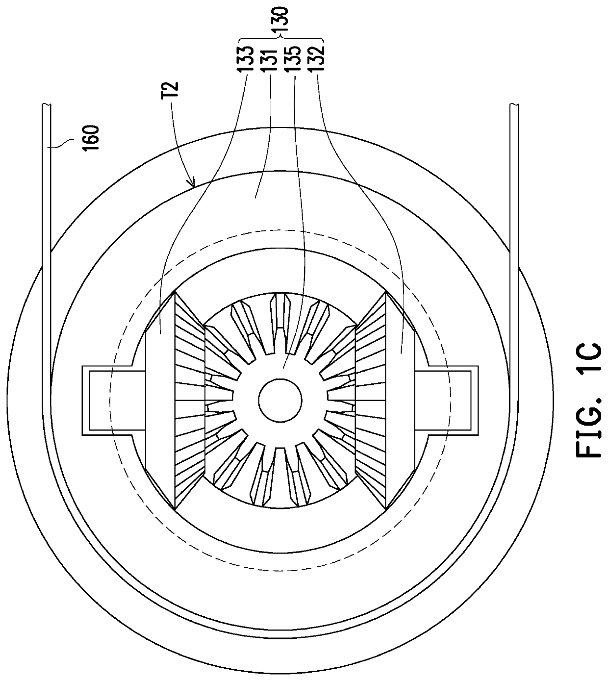
[0018]FIG. 1A is a perspective schematic view of a dual-motor differential drive system according to an embodiment of the disclosure. FIG. 1B is an exploded schematic view of some components of the dual-motor differential drive system in FIG. 1A. FIG. 1C is a schematic cross-sectional view of the dual-motor differential drive system in FIG. 1A along the A-A line. FIG. 1D is a schematic cross-sectional view of the dual-motor differential drive system in FIG. 1A along the B-B line.

[0019]With reference to FIG. 1A, the dual-motor differential drive system of the disclosure is, for example, applied to a two-wheeled electric car. A main wheel shown in FIG. 1A may be a front wheel of the electric car or a rear wheel of the electric car, but the disclosure is not limited thereto.

[0020]With reference to FIGS. 1A to 1D, a dual-motor differential drive system 100 of the disclosure includes a main wheel 110, a drive wheel 120, a differential unit 130, a first motor 140, a second motor 150, and ...


PUM


Abstract

A dual-motor differential drive system, including a main wheel, a drive wheel, a differential unit, a first motor, a second motor, and at least one drive unit, is provided. The main wheel has a central shaft. The drive wheel is disposed on the main wheel. The differential unit is disposed on a side of the drive wheel and aligned with the drive wheel. The first motor and the second motor respectively have a first shaft and a second shaft, and are connected to the differential unit. The at least one drive unit is disposed on the differential unit and the drive wheel. The first motor and the second motor are adapted to run in same or reverse direction to respectively drive the differential unit to rotate. The differential unit drives the drive wheel through the at least one drive unit, enabling the main wheel to pivot through the central shaft.

Description

BACKGROUNDTechnical Field[0001]This disclosure relates to a differential drive system, and in particular to a dual-motor differential drive system that is applicable to electric vehicles.Description of Related Art[0002]Most of the existing electric locomotives use a single motor or double motors. In order to achieve the best working efficiency of the motor, a gearbox is required to adjust the best rotational speed of the motor. With the increase in power demand, the electric control system has to use high-power components, causing the manufacturing cost of the drive system to increase. In addition, the usage of the gearbox increases the complexity of the drive mechanism and also increases the frictional work consumption between the gears. The existing single-motor drive system requires the usage of a water cooling device, which leads to high cost and high power consumption in the single-motor drive system.[0003]Nowadays, a dual-motor drive system has also been developed to improve t...

Claims


Application Information

Patent Timeline
IPC IPC(8): B60K1/02B60K17/16
CPCB60K1/02F16H7/02B60K17/16B62M23/02
Inventor YANG, YING-CHUNG
Owner YANG YING CHUNG
Learn More