Hybrid vehicle drive system and method for fuel reduction during idle

a hybrid vehicle and drive system technology, applied in the direction of engine-driven generator propulsion, external condition input parameters, navigation instruments, etc., can solve the problems of lack of no-idle system, inability to optimize engine operation, and need to reposition existing drive train components

Pending Publication Date: 2022-05-19
POWER TECH HLDG LLC
View PDF0 Cites 8 Cited by
  • Summary
  • Abstract
  • Description
  • Claims
  • Application Information

AI Technical Summary

Benefits of technology

[0024]In some embodiments, a second transmission fluid pump provides a flow of fluid through a component (e.g., a power take off). The pump is driven by an electric motor and the flow of fluid helps to cool the component. In some embodiments, the second pump operates when the chassis is stationary, and the second pump operates when the second prime mover operates.

Problems solved by technology

One limitation of this system is that the second prime mover is typically positioned between the first prime mover and the transmission, creating the need to reposition existing drive train components.
However, series design hybrids also generally include a larger, heavier battery; have a greater demand on the engine to maintain the battery charge; and include inefficiencies due to the multiple energy conversions.
However, parallel design hybrids typically lack a no-idle system and may have non-optimal engine operation (e.g., low rpm or high transient loads) under certain circumstances.
Sophisticated power train control systems and power management systems required for the operation of a hybrid vehicle drive system can add cost and complexity.

Method used


Image

  • Hybrid vehicle drive system and method for fuel reduction during idle
  • Hybrid vehicle drive system and method for fuel reduction during idle
  • Hybrid vehicle drive system and method for fuel reduction during idle

Examples


Embodiment Construction

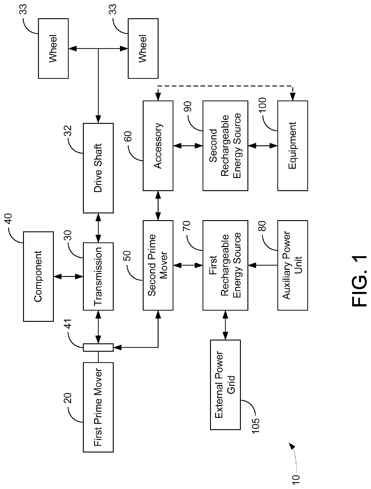
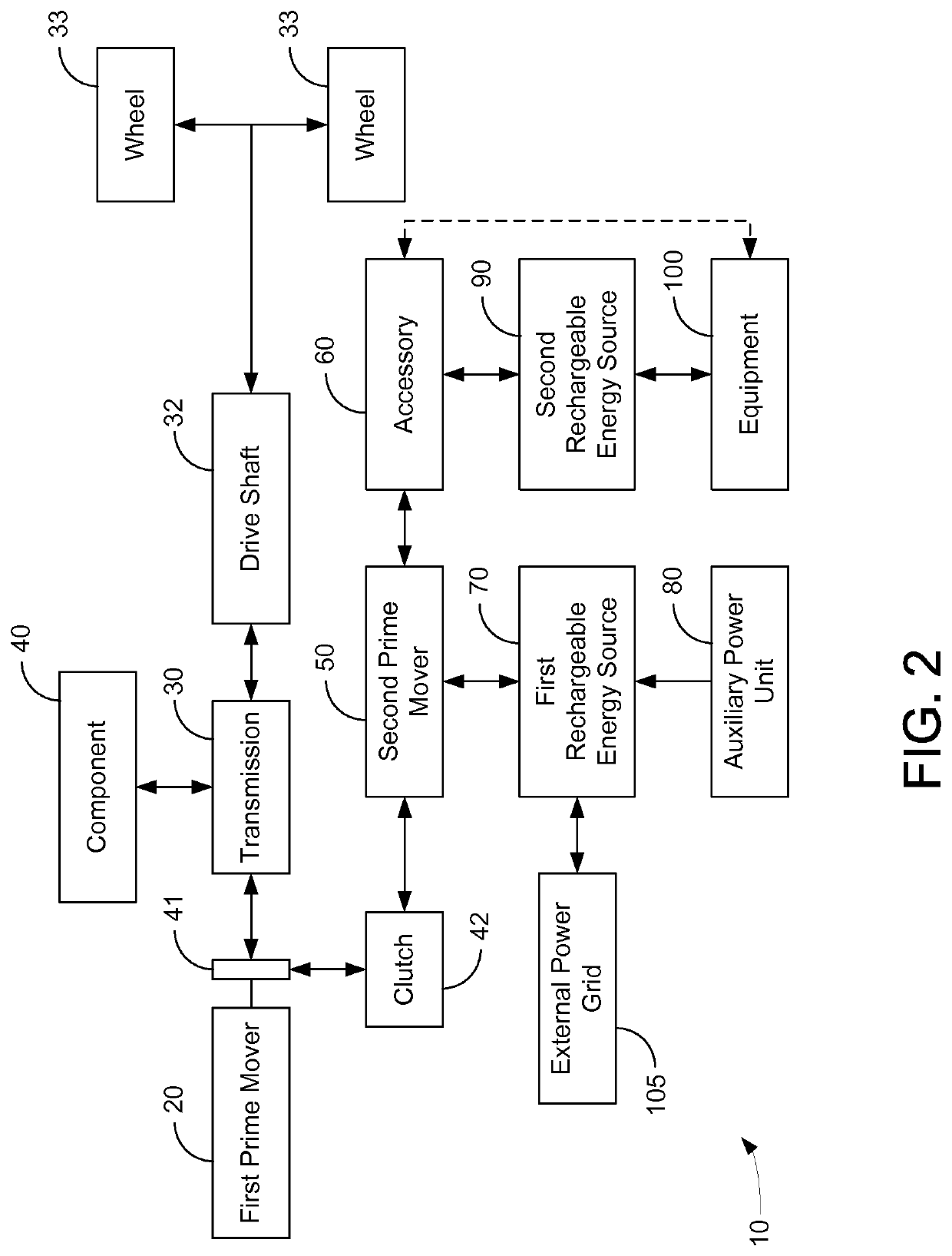
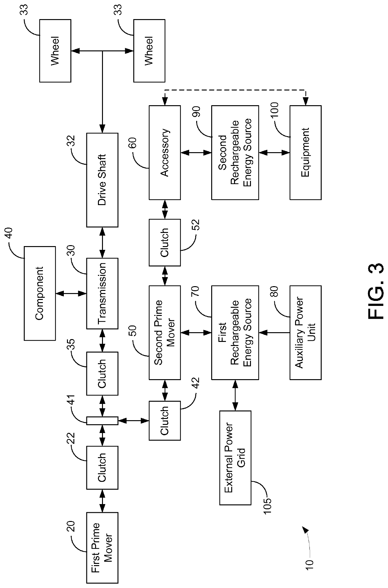
[0034]Hybrid vehicle drive systems according to several possible embodiments are presented. One feature of one exemplary embodiment of the hybrid vehicle drive system is that the hybrid drive system can utilize an interface between the first prime mover and the transmission without using a PTO. Alternatively, one exemplary embodiment of the hybrid vehicle drive system is that the hybrid drive system can utilize a PTO interface to drive electrical or hydraulic motors as discussed in the PTO hybrid architectures discussed in the applications incorporated herein by reference. Another feature of one embodiment is that a drive shaft can be powered singly or in any combination by a first prime mover, a second prime mover, and an accessory using the interface or the PTO interface. Preferred embodiments incorporate hydraulic systems into the hybrid vehicle drive system for optimal energy storage and usage. It is noted that the term motor as used herein refers to a motor / generator or motor / p...


PUM

PropertyMeasurementUnit
axle weight ratingaaaaaaaaaa
heightaaaaaaaaaa

Abstract

A vehicle drive system for a vehicle including a first prime mover, a first prime mover driven transmission, and a rechargeable power source can be configured for reduced fuel consumption at idle. The vehicle drive system includes an electric motor in direct or indirect mechanical communication with the first prime mover. The control system causes fuel to be eliminated to the first prime mover while the vehicle is stopped and causes the electric motor to rotate the first prime mover at a speed, thereby reducing fuel consumption at idle for the vehicle.

Description

CROSS-REFERENCE TO RELATED PATENT APPLICATIONS[0001]This application is a continuation-in-part of U.S. application Ser. No. 15 / 588,232, filed May 5, 2017, now U.S. Pat. No. 11,225,240 which is a continuation of U.S. application Ser. No. 14 / 745,232, filed Jun. 19, 2015, (096637-0170), now U.S. Pat. No. 9,643,593 which is a continuation of U.S. application Ser. No. 14 / 081,892 filed Nov. 15, 2013, now U.S. Pat. No. 9,061,680, which is a Continuation-In-Part of US Application PCT / US2013 / 036431, filed Apr. 12, 2013 which claims priority to Provisional Application U.S. Application 61 / 624,118, filed Apr. 13, 2012, all of the above patent applications and patents are incorporated herein by reference in their entireties. This application is also a continuation-in-part of U.S. application Ser. No. 15 / 067,419 filed Mar. 11, 2016 which is a continuation of U.S. application Ser. No. 13 / 812,723 filed Jan. 28, 2013, now U.S. Pat. No. 9,283,954, which claims priority to PCT Application 2012 / 029835,...

Claims


Application Information

Patent Timeline
Patent Type & Authority Applications(United States)
IPC IPC(8): B60L1/00B60W20/11H01M10/48H01M16/00G01C21/34B60W20/12B60W50/00B60W20/00B60L58/12B60W10/06H01M10/44B60L1/14B60L53/24B60W10/26B60W10/08
CPCB60L1/003B60W2556/10H01M10/48H01M16/006G01C21/3469B60W20/12B60W50/0097B60W20/00B60L58/12B60W10/06H01M10/44B60L1/14B60L53/24B60W10/26B60L1/006B60L2260/54Y02T10/62Y10S903/93B60W2710/244B60L2240/622B60L2260/52B60L2240/70B60W2556/45Y02T10/72B60Y2200/41B60W10/08Y02T90/16Y10S903/903Y02T10/70B60W20/11B60W30/1888Y02E60/10Y02E60/50Y02T10/7072Y02T90/14B60L50/16B60L50/61B60L55/00B60L2240/423B60L50/40B60W20/15B60W20/10B60W20/16B60W30/18054B60W30/194B60Y2300/474B60W2710/0694H02J7/1423H02J7/1438B60W2510/244B60W2510/305B60W2520/04B60W2710/083B60W2710/0666
Inventor DALUM, JOSEPH T.
Owner POWER TECH HLDG LLC
Why Eureka
Try Eureka