Turbine stator blade and steam turbine

Active Publication Date: 2022-05-19
MITSUBISHI HEAVY IND LTD
View PDF0 Cites 2 Cited by
  • Summary
  • Abstract
  • Description
  • Claims
  • Application Information

AI Technical Summary

Benefits of technology

The present invention provides a turbine stator blade that collects droplets more efficiently and a steam turbine that includes this blade.

Problems solved by technology

Since the peripheral speed of the turbine rotor blade may exceed the speed of sound, when scattered droplets collide with the turbine rotor blades, the outer surfaces thereof may be eroded and erosion may occur.
In addition, rotation of the turbine rotor blades may be hindered due to collisions of droplets, thereby resulting in braking loss.

Method used


Image

  • Turbine stator blade and steam turbine
  • Turbine stator blade and steam turbine
  • Turbine stator blade and steam turbine

Examples


first embodiment

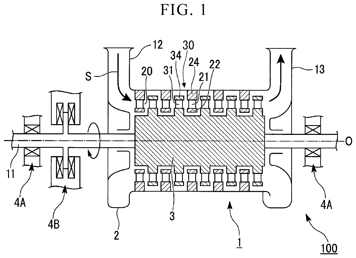
[0034]A first embodiment of the present invention will be described with reference to FIGS. 1 to 4. A steam turbine 100 according to the present embodiment includes a steam turbine rotor 3 that extends in an axis O direction, a steam turbine casing 2 that covers the steam turbine rotor 3 from an outer circumferential side, and a journal bearing 4A and a thrust bearing 4B that support a shaft end 11 of the steam turbine rotor 3 such that it can rotate around the axis O.

[0035]The steam turbine rotor 3 has a rotary shaft 1 which extends along the axis O, and a plurality of rotor blades 30 which are provided on an outer circumferential surface of the rotary shaft 1. The plurality of rotor blades 30 are arranged in a circumferential direction of the rotary shaft 1 with a constant gap therebetween. Also in the axis O direction, the plurality of rotor blades 30 are arranged in a row with a constant gap therebetween. Each of the rotor blades 30 has a rotor blade main body 31 (turbine rotor ...

second embodiment

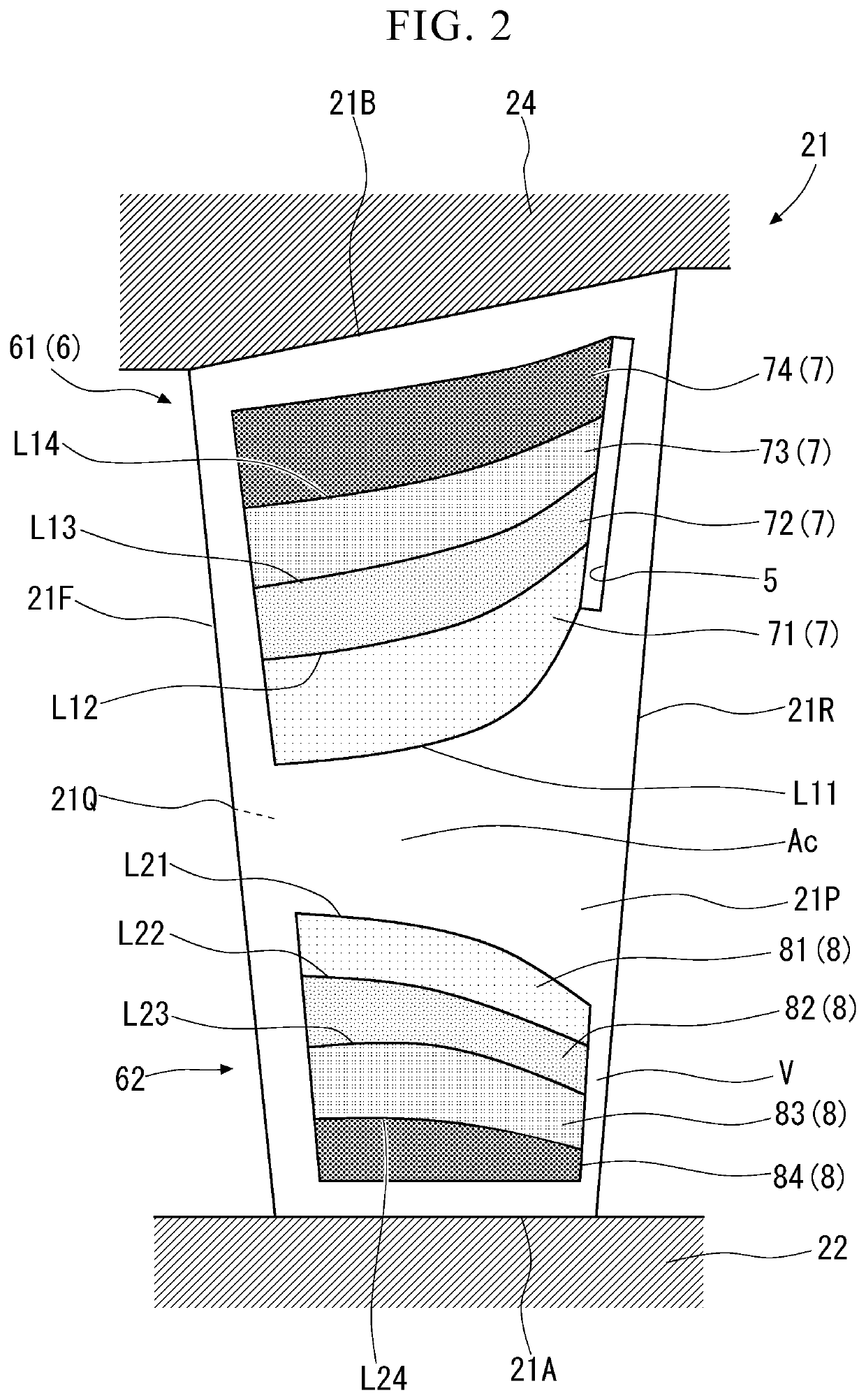
[0061]Next, a second embodiment of the present invention will be described with reference to FIG. 5. The same reference signs are applied to constitutions similar to those of the foregoing first embodiment, and detailed description will be omitted. As illustrated in FIG. 5, in the present embodiment, constitutions of an outer fine uneven region 61′ and an inner fine uneven region 62′ are different from those of the first embodiment.

[0062]In the outer fine uneven region 61′, the first outer region 71 and the third outer region 73 are hydrophilic similar to the first embodiment. On the other hand, a second outer region 72′ and a fourth outer region 74′ serve as water-repellent regions 9 having water-repellency. In the inner fine uneven region 62′, the first inner region 81 and the third inner region 83 are hydrophilic similar to the first embodiment. On the other hand, a second inner region 82′ and a fourth inner region 84′ serve as the water-repellent regions 9 having water-repellenc...

third embodiment

[0065]Subsequently, a third embodiment of the present invention will be described with reference to FIG. 6. The same reference signs are applied to constitutions similar to those of each of the foregoing embodiments, and detailed description will be omitted. As illustrated in FIG. 6, in the present embodiment, a super water-repellent region 10 having higher water-repellency (super water-repellency) than the pressure side 21P is formed in the gap V between the slit 5 and the trailing edge 21R. Here, the aforementioned state “having super water-repellency” indicates a state in which a contact angle of droplets attached to the super water-repellent region 10 is 150° or larger. The super water-repellent region 10 expands on the downstream side (toward trailing edge 21R side) adjacent to the end edge of the slit 5 on the downstream side thereof.

[0066]According to the foregoing constitution, the super water-repellent region 10 is formed in the gap V between the slit 5 and the trailing edg...


PUM


Abstract

A turbine stator blade (21) includes a pressure side (21P) extending in a radial direction intersecting a flowing direction of steam and facing upstream in the flowing direction. A slit (5) capturing droplets generated by liquefaction of the steam is formed on a downstream side of the pressure side (21P). A fine uneven region (6), which guides the droplets attached to the pressure side (21P) in the radial direction such that the droplets are moved toward the slit (5) and from upstream toward downstream, is formed in a further upstream position than the slit (5). The fine uneven region (6) has a flow resistance to the droplets gradually increasing from inward to outward in the radial direction.

Description

TECHNICAL FIELD[0001]The present invention relates to a turbine stator blade and a steam turbine.[0002]This application claims priority based on Japanese Patent Application No. 2019-033540, filed Feb. 27, 2019, the content of which is incorporated herein by reference.BACKGROUND ART[0003]A steam turbine includes a rotary shaft that is rotatable around an axis, a plurality of turbine rotor blade stages that are arranged in a direction of the axis on an outer circumferential surface of the rotary shaft with a gap therebetween, a casing that covers the rotary shaft and the turbine rotor blade stages from an outer circumferential side, and a plurality of turbine stator blade stages that are alternately arranged with the turbine rotor blade stages on an inner circumferential surface of the casing. An intake port for taking in steam from outside is formed on an upstream side of the casing, and an exhaust port is formed on a downstream side of the casing. A flowing direction and a speed of ...

Claims


Application Information

Patent Timeline
IPC IPC(8): F01D9/04
CPCF01D9/041F01D25/32F05D2300/51F05D2300/512F05D2220/31F05D2240/123F01D9/02F05D2260/602F01D5/141F01D5/147F05D2240/122
Inventor MIZUMI, SHUNSUKEDUAN, CHONGFEISASAO, YASUHIROTABATA, SOICHIRO
Owner MITSUBISHI HEAVY IND LTD
Why Eureka
Try Eureka