Paper discharge device

Inactive Publication Date: 2011-08-18
SEIKO INSTR INC
View PDF5 Cites 1 Cited by
  • Summary
  • Abstract
  • Description
  • Claims
  • Application Information

AI Technical Summary

Benefits of technology

[0016]The present invention has been made in view of the above-mentioned circumstances, and has an object to provide a paper discharge device, which is capable of efficiently collecting a large amount of paper, and also capable of allowing the paper in a waiting state to wait without being brought into contact with collected paper until operations such as printing are ended.

Problems solved by technology

However, in the above-mentioned conventional paper discharge device, there still remain the following problems.
For that reason, the paper is inevitably liable to impart the rounding in the conveying direction (paper curling).
Therefore, there were great many cases where the collected paper do not keep the level state within the collection space, and were rounded due to the paper curling.
For that reason, as the paper becomes bulky, it is difficult to efficiently collect the large amount of the paper within the collection space.
In this case, when the paper which has already been collected are bulky due to paper curling within the collection space, the paper in a waiting state are liable to be entangled with the collected paper, and there was a risk of causing paper jam.

Method used


Image

  • Paper discharge device
  • Paper discharge device
  • Paper discharge device

Examples


Embodiment Construction

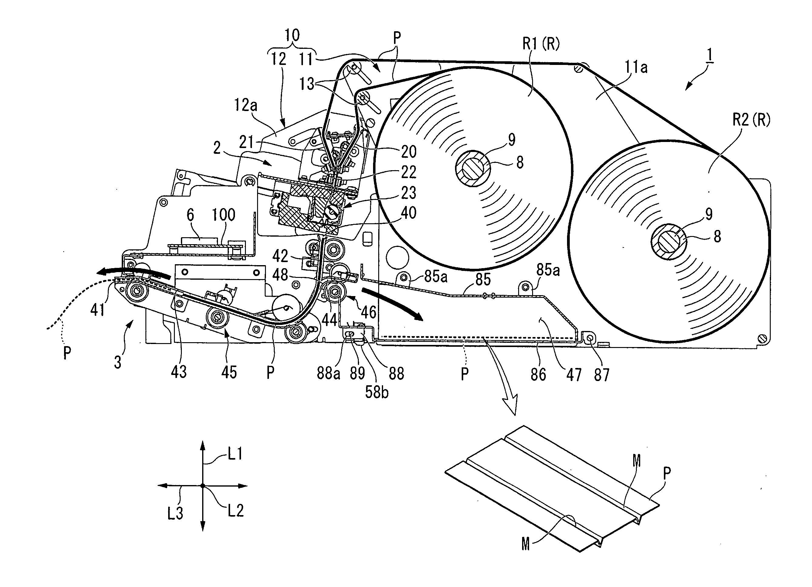
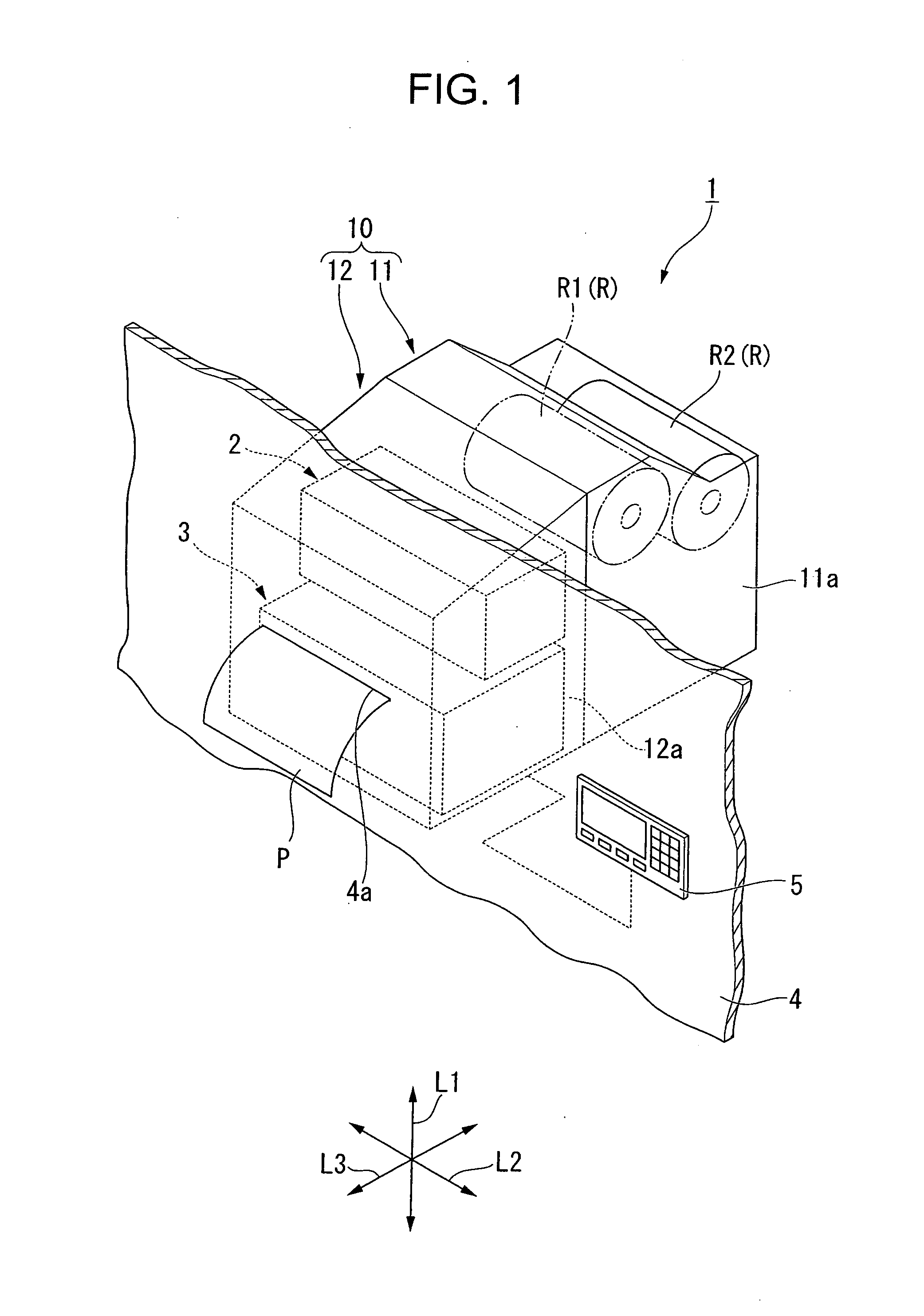
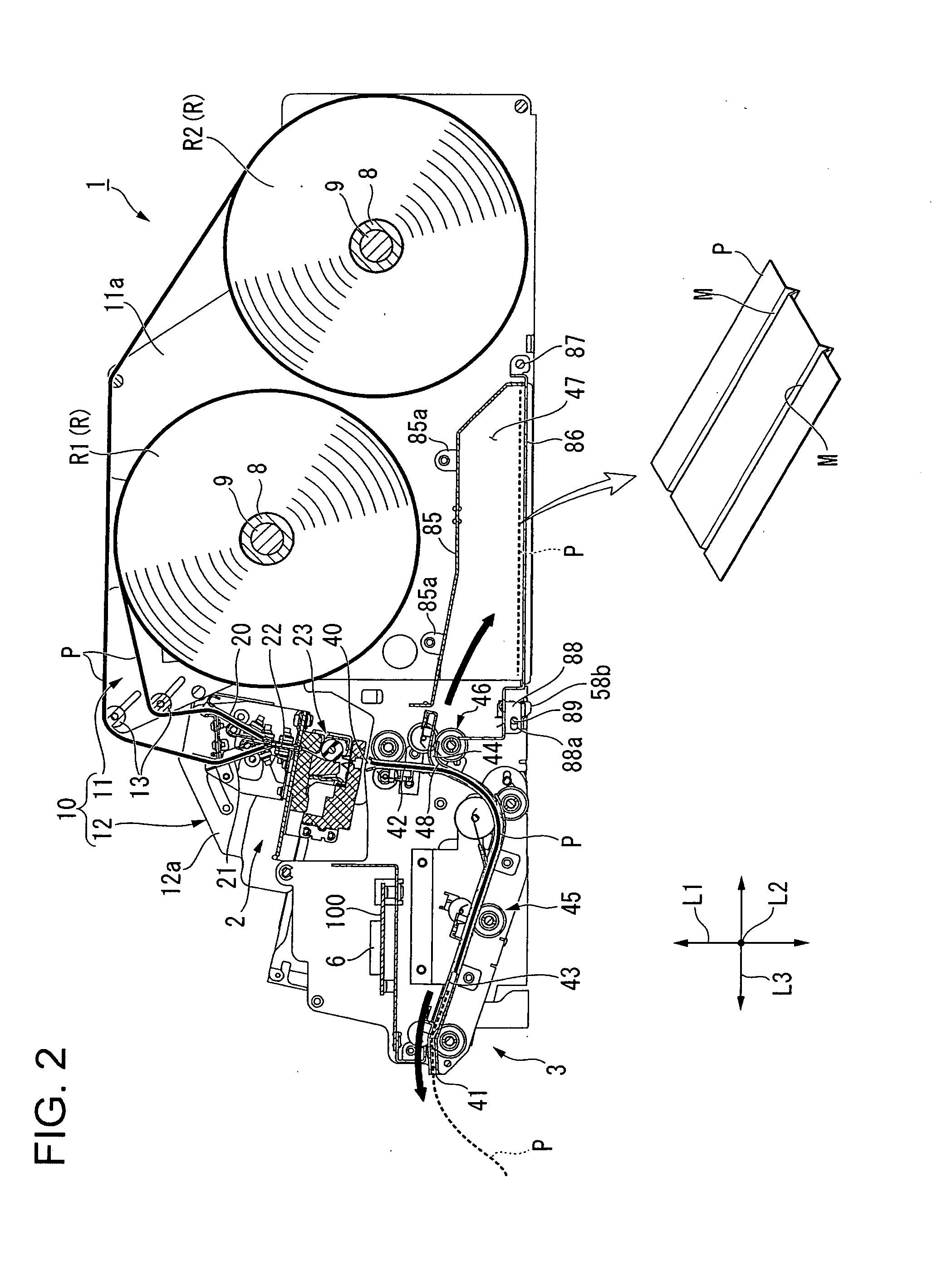
[0050]Hereinafter, an embodiment of the present invention is described with reference to FIG. 1 to FIG. 10. Note that, in this embodiment, as illustrated in FIG. 1, description is made of a printer 1 by way of example, into which a print unit 2, and a paper discharge unit (paper discharge device) 3 are integrally incorporated.

[0051]Note that, FIG. 1 is a perspective view schematically illustrating an overall outer appearance of the printer 1.

[0052]The printer 1 is usually used, for example, by being incorporated into an automated teller machine (ATM), a cash dispenser (CD), and the like, and is installed so as to be brought into contact with an inner side of an enclosure 4 of the ATM or CD. Then, a paper (statement of account, etc.) P, which is printed and discharged by the printer 1, is discharged through an eject port 4a formed in the enclosure 4 so as to be delivered to a user.

[0053]Note that, the printer 1 is configured to operate based on an instruction input by, for example, a...


PUM


Abstract

Provided is a paper discharge device (1) capable of efficiently collecting the large amount of the paper, and of allowing the paper in the waiting state to wait without being brought into contact with the collected paper until the processings such as printing are ended. The paper discharge device (1) includes: a waiting path (43), one side of which is connected to the input port (40) and another side of which is connected to the discharge port (41); a collection path (44), one side of which is connected to the waiting path through a merged portion (48) and another side of which is connected to the collection chamber (47); conveyance mechanisms (45) for conveying the paper which was conveyed through the input port until the discharge port in a forward direction, and for conveying, after lapse of a given period of time after the conveyance of the paper, the paper in a reverse direction through the merged portion to feed into the collection path; and an input mechanism (46) provided in the collection path, for conveying the paper fed from the waiting path toward a downstream side to throw into the collection chamber, in which the input mechanism, includes one side of rollers and another side of rollers which rotate while sandwiching the paper between the one side of rollers and the another side of rollers, and conveys the paper while forming folds (M) across a total length of the paper along a conveying direction by the both rollers.

Description

BACKGROUND OF THE INVENTION[0001]1. Field of the Invention[0002]The present invention relates to a paper discharge device, which discharges received paper from a discharge port.[0003]2. Description of the Related Art[0004]At present, there exist many devices (apparatus), which are designed so as to automatically deliver to users various paper such as passes of toll roads, admission tickets of various facilities, or rail road tickets of various transportation, and statements of account, etc. issued from automated teller machines (ATM), cash dispensers (CD), or the like. In general, a paper discharge device is incorporated into those devices, which conveys the paper, after receiving the paper printed by a printer, or the like, to a discharge port, and discharges the printed paper from the discharge port.[0005]By the way, there are many cases where personal information, confidential matters, or the like of the user may be printed on the paper to be delivered to the user. For example, o...

Claims


Application Information

Patent Timeline
IPC IPC(8): B65H29/20
CPCG07F19/20G07G5/00G07F19/201
Inventor TOZAKI, SHUJISEINO, TAKUMI
Owner SEIKO INSTR INC
Why Eureka
Try Eureka