Map-information obstacle-tracking system and method

a mapping and obstacle technology, applied in the direction of vehicle position/course/altitude control, process and machine control, instruments, etc., can solve the problems of system inability to ascertain when the obstacle is (i.e. the front car), and the accuracy of the detection results of the curved lanes can be unstabl

Active Publication Date: 2022-05-26
AUTOMOTIVE RES & TESTING CENT
View PDF0 Cites 3 Cited by
  • Summary
  • Abstract
  • Description
  • Claims
  • Application Information

AI Technical Summary

Benefits of technology

[0007]Yet another objective of the present invention is to provide a map-information obstacle-tracking system and method, wherein even though the obstacle exceeds the preset region of interest (ROI) of the sensor, the present invention can still predict the planned routes of the obstacle (front car) and match the obstacle with the front candidate routes to predict the moving trajectory of the obstacle without system dissociation.
[0009]According to one embodiment of the present invention, the vehicular dynamic positioning module may further acquire the state of the vehicle, including the speed, orientation, position, and moving direction of the vehicle.

Problems solved by technology

However, the conventional driver assistance systems still have drawbacks in the car-following models on curved lanes.
For example, while a front car has not entered a curved lane yet or has entered a curved lane, the system cannot ascertain when the obstacle (i.e. the front car) will turn into a curved lane for the first time or turn its direction once again.
Consequently, the accuracy of the detection results of the curved lanes can be unstable.
In the conventional detection systems, the factors may cause following unstable detection results: 1. Limited viewing angle and visible distance of a camera affects the identification of traffic lanes and obstacles; 2. Steel rods and guardrails are likely to affect radars and cause misjudgments; 3. The appearance distortion of the obstacle on a curved lane detected by a lidar uphill is larger than that one a straight road.

Method used


Image

  • Map-information obstacle-tracking system and method
  • Map-information obstacle-tracking system and method
  • Map-information obstacle-tracking system and method

Examples


Embodiment Construction

[0026]The present invention provides a map-information obstacle-tracking system and method thereof, wherein the map-information obstacle-tracking system is installed on a vehicle, and is arranged to integrate map-information routes to obtain the information such as the curvatures, slopes, etc. of the curved road ahead, in order to approximate the current position of the obstacle previously predicted by a Kalman filter, making the prediction result matches the actual position of the obstacle even more.

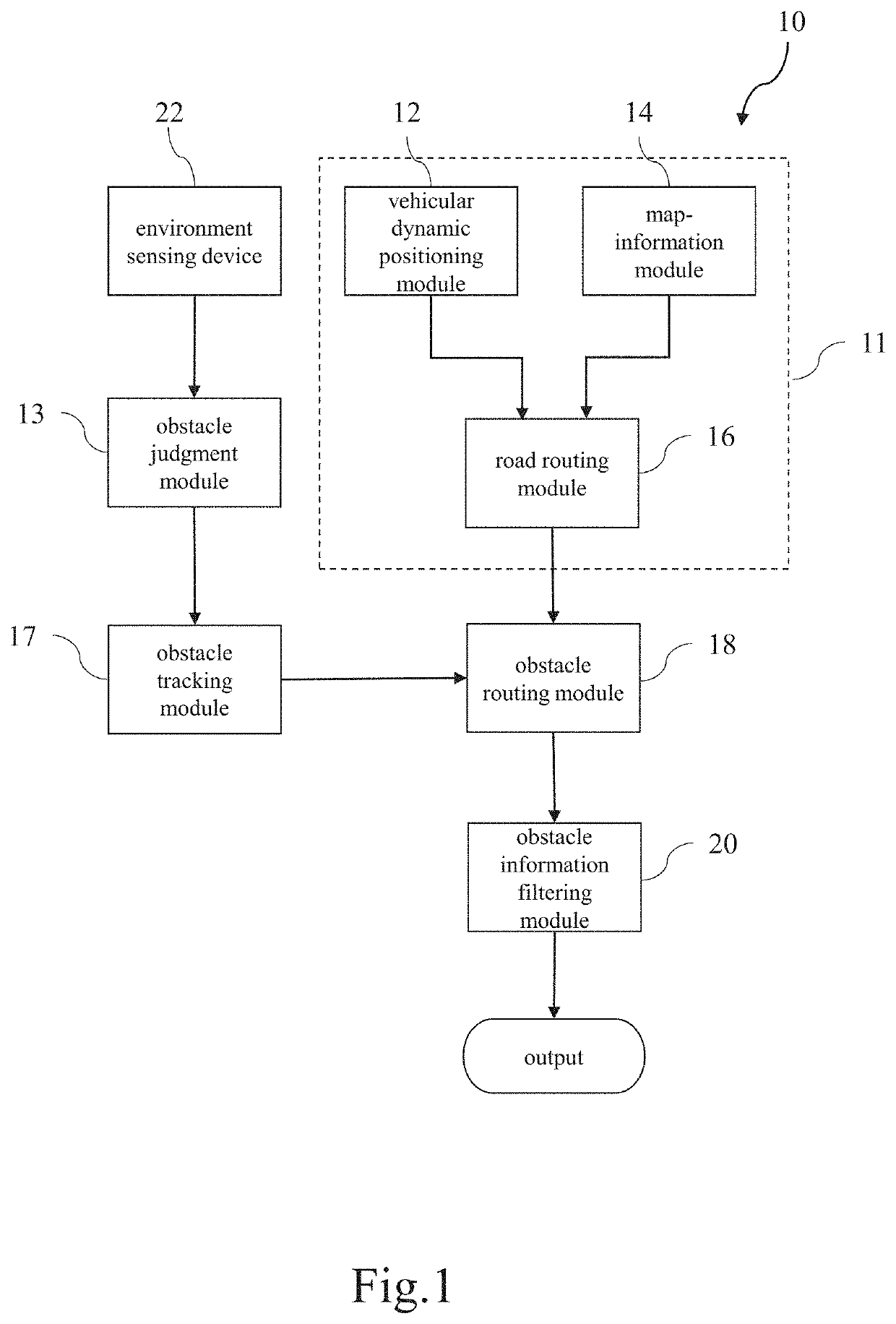
[0027]Refer to FIG. 1. FIG. 1 is a block diagram schematically showing the map-information obstacle-tracking system according to one embodiment of the present invention. The map-information obstacle-tracking system 10 of the present invention comprises a pre-processing module 11, an obstacle judgment module 13, an obstacle tracking module 17, an obstacle routing module 18, and an obstacle information filtering module 20. The pre-processing module 11 includes a vehicular dynamic position...


PUM


Abstract

A map-information obstacle-tracking system and a method thereof are provided. The system is installed in a vehicle. The method includes: using a vehicular dynamic positioning module to acquire a position of a vehicle, and using a map-information module to acquire map-information routes of an area neighboring the position of the vehicle; comparing position of the vehicle with the map-information routes to find out candidate routes in the moving direction of the vehicle; determining one of the candidate routes where said obstacle appears, and predicting a moving trajectory of the obstacle; estimating and outputting a position of the obstacle. The present invention is characterized in using map-information and able to acquire the curvature and slope of the front curved lane. Therefore, the present invention can improve the precision of the obstacle position and stabilizes the accuracy of detecting an obstacle in a curved lane.

Description

BACKGROUND OF THE INVENTIONField of the Invention[0001]The present invention relates to a driver assistance technology, particularly to a map-information obstacle-tracking system and method thereof.Description of the Prior Art[0002]The driver assistance system of vehicles can detect obstacles ahead and use a filter mechanism to estimate the current positions of the obstacles according to the information of the obstacles in the past time points. However, the conventional driver assistance systems still have drawbacks in the car-following models on curved lanes. For example, while a front car has not entered a curved lane yet or has entered a curved lane, the system cannot ascertain when the obstacle (i.e. the front car) will turn into a curved lane for the first time or turn its direction once again. Thus, the predicted position of the obstacle has larger deviation with respect to the real position of the obstacle. Consequently, the accuracy of the detection results of the curved lan...

Claims


Application Information

Patent Timeline
Patent Type & Authority Applications(United States)
IPC IPC(8): G05D1/02
CPCG05D1/0214G05D1/0251G05D2201/0213G05D1/0274B60W30/16B60W2552/53B60W2556/40B60W2554/4041B60W2520/10B60W2556/50B60W2552/30B60W2552/10B60W2552/15B60W2554/802B60W2554/806G08G1/166G01C21/30
Inventor CHEN, YING-RENSIAO, SIANG-MIN
Owner AUTOMOTIVE RES & TESTING CENT
Why Eureka
Try Eureka