
Rear carrier system for a motor vehicle

a rear carrier and motor vehicle technology, applied in the direction of vehicle components, transportation and packaging, supplementary fittings, etc., can solve the problem of inability to change the orientation of the angled par

Active Publication Date: 2022-06-09
ATERA
View PDF13 Cites 1 Cited by
  • Summary
  • Abstract
  • Description
  • Claims
  • Application Information

AI Technical Summary

Benefits of technology

The invention is a rear carrier system for vehicles that allows for easy mounting and dismantling of carrier components. The system includes carrier profiles that are designed to be fixed relative to each other in a way that they cannot be changed in terms of orientation. The carrier profiles can be designed as a single part or multi-part design, with the parts assigned to each other in a fixed and dimensionally stable manner. The carrier profiles have complementary support profilings that form a carrier portion for holding functional components of the rear carrier system. The support profilings can be designed to form a common carrier contour for fastening a holding device without structural changes to the carrier profiles. The fastening profiling of each carrier profile and the assigned carrier receiver are designed as complementary bayonet closure portions that align with the other carrier profile when rotated to their ready-for-operation mounted end position. This allows for a simple and secure mounting and dismantling of the carrier components.

Problems solved by technology

The angled orientation is not able to be changed, due to the dimensionally stable design of the carrier profile.
As a result, a particularly simple mounting and dismantling of the carrier functional components of the rear carrier system is achieved, since the two carrier profiles merely have to be inserted with their first profile limbs into the carrier receivers and then have to be rotated toward a vehicle center, whereby the positive overlap and blocking of the support profilings relative to one another inevitably results.

Method used


Image

  • Rear carrier system for a motor vehicle
  • Rear carrier system for a motor vehicle
  • Rear carrier system for a motor vehicle

Examples


Embodiment Construction

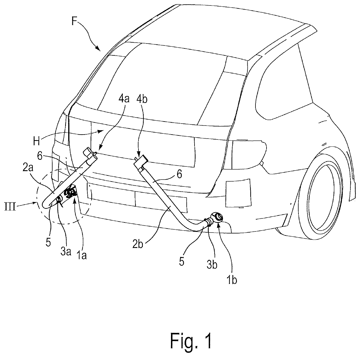
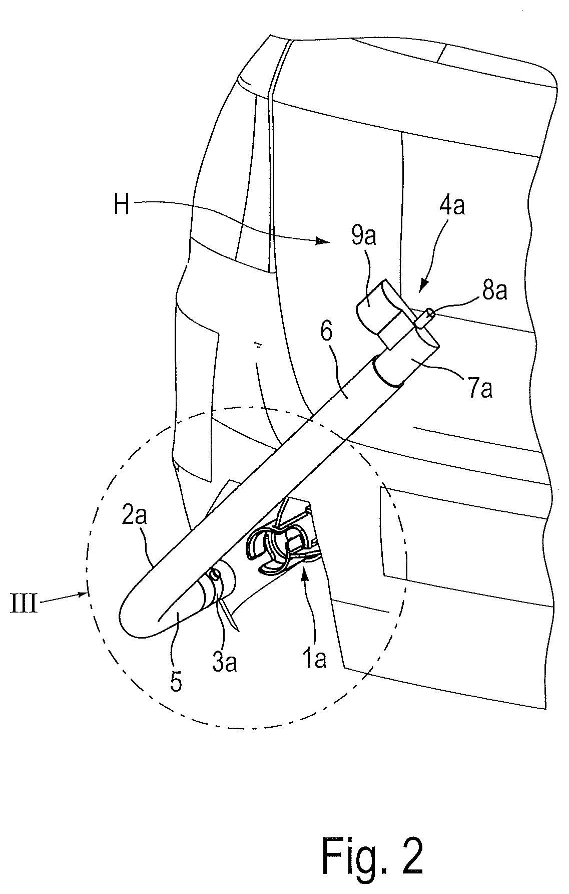
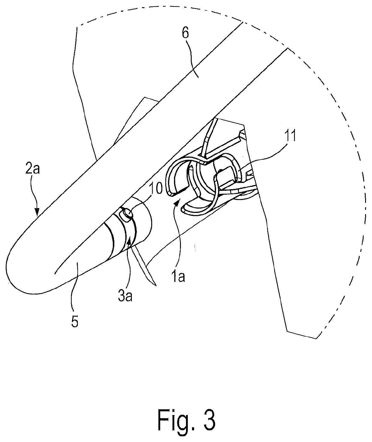
[0027]A passenger motor vehicle F has a rear region H to which a rear carrier system, described hereinafter in more detail with reference to FIGS. 1 to 9, is assigned. The passenger motor vehicle F is provided with a body supporting structure which in a rear region of the passenger motor vehicle F has corresponding body carrier parts such as, in particular, body crossmembers and body longitudinal members. The rear-side body carrier parts of the body supporting structure are concealed in the rear region H of the passenger motor vehicle F by rear cladding parts, such as in particular a rear fender. The rear cladding parts, not denoted in more detail, have on two opposing sides and level with the rear fender circular through-holes which may be concealed by cover panels, not shown in more detail. In each case a carrier receiver 1a which is fixed to the vehicle is provided, said carrier receiver being connected fixedly and in a force-transmitting manner to a body carrier part of the body...


PUM


Abstract

Rear carrier system for a motor vehicle having two carrier receivers which are fixed to the vehicle, and having two carrier profiles which are provided on vehicle-side end regions in each case with a fastening profiling. In a ready-for-operation mounted state, each carrier profile is releasably fastened with the fastening profiling to the assigned carrier receiver. Each carrier profile is provided at a distance from the fastening profiling with a support profiling, wherein in the ready-for-operation mounted state of the carrier profiles the support profilings are positively supported against one another.

Description

CROSS-REFERENCE TO RELATED APPLICATION[0001]This claims priority from German Application No. 10 2020 215 454.6, filed Dec. 8, 2020, the disclosure of which is hereby incorporated by reference in its entirety.TECHNICAL FIELD[0002]The invention relates to a rear carrier system for a motor vehicle having two carrier receivers which are fixed to the vehicle, and having two carrier profiles which are provided on vehicle-side end regions in each case with a fastening profiling, in the ready-for-operation mounted state each carrier profile being releasably fastened thereby to the assigned carrier receiver.BACKGROUND AND SUMMARY[0003]Such a rear carrier system is disclosed in DE 10 2004 033 809 A1. To this end, a passenger motor vehicle has two carrier receivers which are fixedly connected to a body supporting structure in the region of a rear-side fender. In an embodiment according to FIG. 6 the carrier receivers are designed as bayonet closure receivers. Each of the two carrier receivers ...

Claims


Application Information

Patent Timeline
Patent Type & Authority Applications(United States)
IPC IPC(8): B60R9/06
CPCB60R9/06B60R9/10
Inventor SCHULZ, ALBERT
Owner ATERA
Learn More