
Sheet-shaped conductive member and manufacturing method therefor

Pending Publication Date: 2022-06-09
LINTEC CORP
View PDF0 Cites 0 Cited by
  • Summary
  • Abstract
  • Description
  • Claims
  • Application Information

AI Technical Summary

Benefits of technology

The patent describes a conductive sheet with wavy linear bodies that improve its stretchability. However, the sheet may not have equal stretchability across the entire surface. For example, the ends of the sheet may need high stretchability, while the center may not. Additionally, patterns or holes can be added to the sheet. The technical effect of this invention is to improve the stretchability of a conductive sheet.

Problems solved by technology

However, it is not indispensable that an entire sheet surface of the conductive sheet has comparable stretchability.

Method used


Image

  • Sheet-shaped conductive member and manufacturing method therefor
  • Sheet-shaped conductive member and manufacturing method therefor
  • Sheet-shaped conductive member and manufacturing method therefor

Examples


first exemplary embodiment

Effects of First Exemplary Embodiment

[0120]The exemplary embodiment can achieve the following effects.

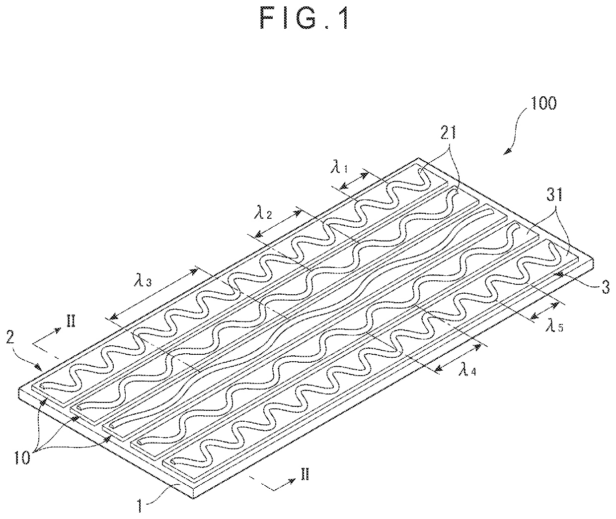
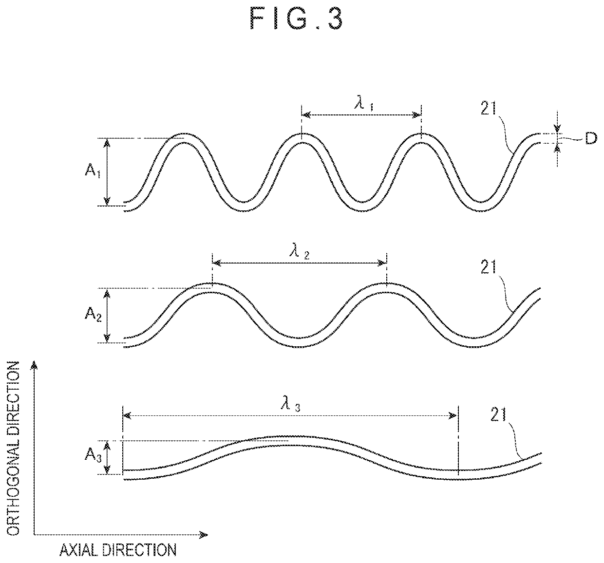
(1) According to the exemplary embodiment, the center portion and the end of the sheet-shaped conductive member 100 may have different levels of stretchability. The stretchability is higher from the center portion toward the end of the sheet-shaped conductive member 100. Accordingly, a property of the sheet (e.g., stretchability) can be designed or determined as needed in each part of the sheet surface.

(2) According to the exemplary embodiment, in the direction orthogonal to the axial direction of the conductive linear bodies 21, the phases of adjacent ones of the conductive linear bodies 21 may be shifted from each other by the half wavelength. This results in an interval between adjacent ones of the conductive linear bodies 21 being larger in some portions than an interval in a case where no phase is shifted. For example, when the holes H are provided in the above portions, the ho...

second exemplary embodiment

Effects of Second Exemplary Embodiment

[0136]The second exemplary embodiment can achieve effects similar to the effects (1) to (4) of the above first exemplary embodiment and the following effect (5). (5) According to the second exemplary embodiment, the electrodes 4 allow the pseudo sheet structure 2 with a low sheet resistance to conduct electricity, making it possible to generate heat. Accordingly, a heat-generating body that can reduce a voltage applied thereto can be obtained.


PUM


Abstract

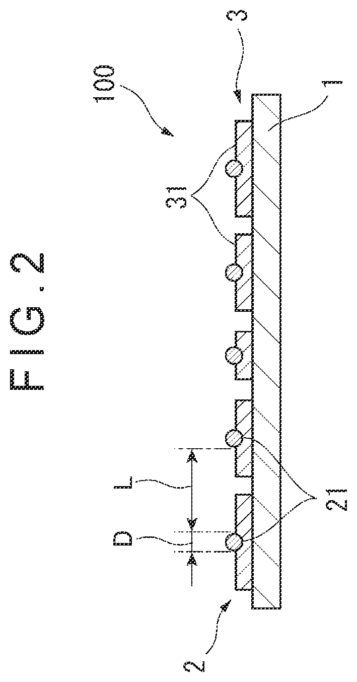
A sheet-shaped conductive member includes: a base material; a resin layer; and a pseudo sheet structure in which a plurality of conductive linear bodies are arranged at an interval, wherein each of the conductive linear bodies has a wavy shape in a plan view of the sheet-shaped conductive member, and in a direction orthogonal to an axial direction of the conductive linear bodies, any adjacent ones of the conductive linear bodies differ from each other in at least one of a wavelength, amplitude, phase or thickness.

Description

TECHNICAL FIELD[0001]The present invention relates to a sheet-shaped conductive member and a manufacturing method therefor.BACKGROUND ART[0002]A sheet-shaped conductive member (hereinafter also referred to as a “conductive sheet”) having a pseudo sheet structure in which a plurality of conductive linear bodies are arranged at an interval therebetween may be applied to components / materials of various articles such as a heat-generating body of a heat-generating device, a material for a heating textile or a display protection film (anti-shatter film).[0003]As a sheet intended to be used as a heat-generating body, Patent Literature 1 describes, for example, a conductive sheet having a pseudo sheet structure in which a plurality of linear bodies extending in one direction are arranged at intervals.CITATION LISTPatent Literature(s)[0004]Patent Literature 1: International Publication No. WO2017 / 086395SUMMARY OF THE INVENTIONProblem(s) to be Solved by the Invention[0005]Patent Literature 1 ...

Claims


Application Information

Patent Timeline
IPC IPC(8): H05B3/22B32B3/14B32B7/025
CPCH05B3/22B32B3/14B32B2457/00B32B2307/302B32B7/025H05B3/34H05B3/145H05B2214/04H05B2203/013H05B2214/02H01B7/06
Inventor MORIOKA, TAKASHIITO, MASAHARU
Owner LINTEC CORP
Learn More