
Color filter substrate and liquid crystal display panel equipped with same

Inactive Publication Date: 2009-01-08
SHARP KK
View PDF10 Cites 14 Cited by
  • Summary
  • Abstract
  • Description
  • Claims
  • Application Information

AI Technical Summary

Benefits of technology

[0016]The present invention has been made in view of the above points, and a main objective of the present invention is to provide a color filter substrate having a structure which can suppress generation of vacuum voids in the one drop filling technique, and suppress an increase in the process time of the injection technique.
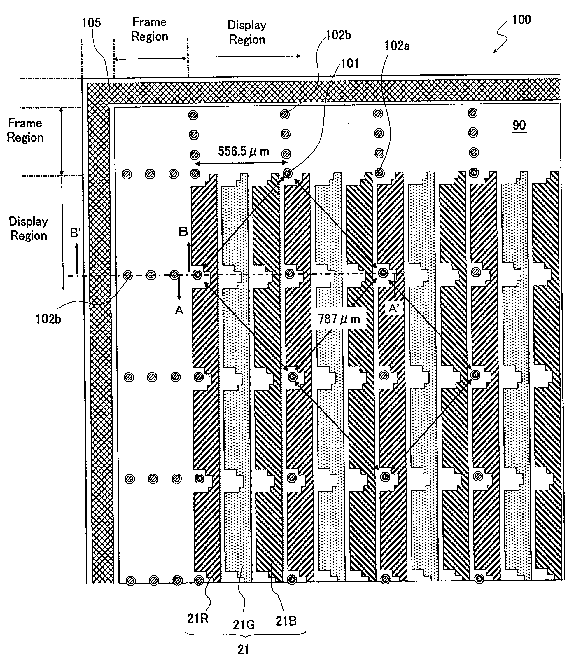
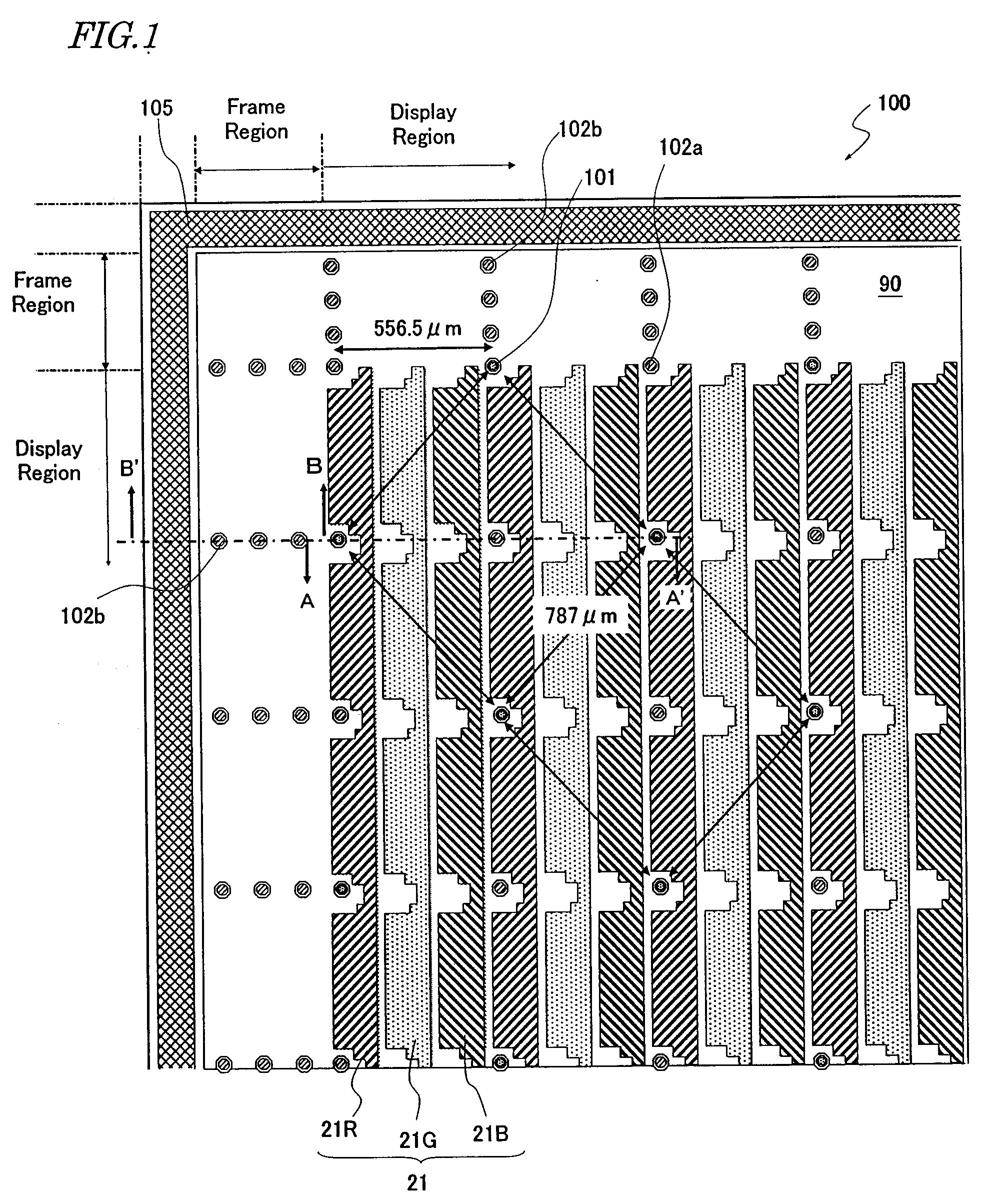
[0017]A color filter substrate according to the present invention is a color filter substrate for use in a liquid crystal display panel, comprising: a transparent substrate; at least three colors of colored layers provided on the transparent substrate; first columnar structure bodies provided in pixel outskirts within a display region, the first columnar structure bodies defining a cell gap; and second columnar structure bodies provided in the pixel outskirts within the display region or outside the display region, the second columnar structure bodies having a smaller height than that of the first columnar structure bodies, such that a difference from the height of the first columnar structure bodies exceeds a range of elastic deformation of the first columnar structure bodies.
[0031]A color filter substrate according to the present invention includes first columnar structure bodies provided in pixel outskirts within a display region, the first columnar structure bodies defining a cell gap, and second columnar structure bodies having a smaller height than that of the first columnar structure bodies, such that a difference from the height of the first columnar structure bodies exceeds a range of elastic deformation of the first columnar structure bodies, the second columnar structure bodies being provided in the pixel outskirts within the display region or outside the display region. The first columnar structure bodies function as columnar spacers, whereas the second columnar structure bodies act to improve the stretchability (spreadability, flowability) of a liquid crystal material. As a result, according to the present invention, generation of vacuum voids in the one drop filling technique and increase in the process time in the injection technique can be suppressed.

Problems solved by technology

In a large-screen liquid crystal panel, it is necessary to set and maintain the thickness of the liquid crystal layer at a predetermined thickness over the entire display region, and thus optimization of the structure and location of the spacers constitutes an important technological problem.
If such an injection technique is adopted in the manufacturing of a large-sized liquid crystal panel, injection of the liquid crystal material takes a long time, thus greatly reducing the production efficiency.
One of the problems of the one drop filling technique is that voids may occur in the liquid crystal layer.
However, through various studies of the inventors, it has been found that voids may occur due to causes which are not even described in the above Patent Documents.
If the liquid crystal material is difficult to stretch (or difficult to spread), there may be local insufficiencies of liquid crystal material, thus causing voids.
On the other hand, if the spacer density is too low, the distance between adjoining spacers becomes longer.
Therefore, an external pressure to the liquid crystal cell, which is associated with the atmospheric pressure when opened to the atmosphere in the injection technique and in the one drop filling technique, will lead to an increased amount of deformation of the spacers and an increased amount of flexure of the glass substrates in between spacers.
This leads to local narrowing of the cell gap, so that vacuum voids become more likely to occur.
Moreover, the distance between adjoining spacers becomes longer with an increase in the size of the liquid crystal display panel (i.e., an increase in pixel size), thus making this problem more outstanding.
Furthermore, in a frame region of the liquid crystal display panel (i.e., a peripheral region of the display region which lies inside the sealing section), there is a large distance between the particulate spacers mixed in the sealant and the spacers within the display region, so that the cell gap locally may become narrow due to flexure of the glass substrates, whereby vacuum voids may become more likely to occur.
Although problems of the one drop filling technique are illustrated above, when the injection technique is used, a decrease in throughput may occur due to the longer injection time of a liquid crystal material.

Method used


Image

  • Color filter substrate and liquid crystal display panel equipped with same
  • Color filter substrate and liquid crystal display panel equipped with same
  • Color filter substrate and liquid crystal display panel equipped with same

Examples


Embodiment Construction

[0043]The present invention is based on a new piece of knowledge which is obtained through vigorous studies by the inventors concerning stretchability of a liquid crystal material.

[0044]Conventionally, in order to ensure that a liquid crystal material is stretchable after the liquid crystal cell is opened to the atmosphere in the vacuum injection technique or the drop injection technique, it has been considered primarily important to maintain the cell gap. Therefore, in order to prevent the cell gap from becoming narrower due to deformation of the spacers or flexure of the glass substrates, methods have been adopted which increase the spacer density, or increase the elastic modulus of the spacers. However, increasing the spacer density actually leads to a greater likelihood of vacuum void generation, as described above.

[0045]Through various experiments, the inventors have found that providing columnar structure bodies which are shorter than columnar spacers (i.e., having a height fo...


PUM


Abstract

A color filter substrate according to the present invention includes a transparent substrate; at least three colors of colored layers provided on the transparent substrate; first columnar structure bodies 101 provided in pixel outskirts within a display region, the first columnar structure bodies 101 defining a cell gap; and second columnar structure bodies 102 provided in the pixel outskirts within the display region or outside the display region, the second columnar structure bodies having a smaller height than that of the first columnar structure bodies 101, such that a difference from the height of the first columnar structure bodies 101 exceeds a range of elastic deformation of the first columnar structure bodies 101.

Description

BACKGROUND OF THE INVENTION[0001]1. Field of the Invention[0002]The present invention relates to a color filter substrate and a liquid crystal display panel including the same.[0003]2. Description of the Related Art[0004]Liquid crystal display devices are characterized by their small size, thinness, low power consumption, and light weight, and therefore are currently in wide use for various electronic devices. In particular, active matrix-type liquid crystal display devices having switching elements are widely adopted in OA devices such as personal computers, AV devices such as television sets, mobile phones, and the like. Moreover, the recent years have seen rapid improvements in display quality, e.g., increase in the size and increase in the definition of liquid crystal display devices, improvements in the pixel effective area ratio (higher aperture ratio), wider viewing angles, or improvements in color purity.[0005]A liquid crystal display device generally includes: a liquid crys...

Claims


Application Information

Patent Timeline
IPC IPC(8): G02F1/1335
CPCG02B5/201G02F1/133514G02F2001/13396G02F1/1341G02F2001/133388G02F1/13394G02F1/133388G02F1/13396G02B5/20G02F1/1335G02F1/1339
Inventor TSUJI, MASAYUKITSUBATA, TOSHIHIDETOKUDA, TSUYOSHI
Owner SHARP KK
Learn More