Steam Generator

Pending Publication Date: 2022-06-16
OTTER CONTROLS LTD
View PDF0 Cites 0 Cited by
  • Summary
  • Abstract
  • Description
  • Claims
  • Application Information

AI Technical Summary

Benefits of technology

The patent is for a device used in industrial applications. The device has an upper portion that is wider than the lower portion. This upper portion has a baffle or mesh filter element that prevents unwanted water droplets from passing through it with the steam. The technical effect of this design is that it allows steam to pass through the upper portion while preventing water droplets from passing through. This improves the quality of the heating process and reduces the likelihood of damage to equipment or workers.

Problems solved by technology

In current steam appliances, the steam generator unit is a limiting feature which dictates the minimum possible size of the appliance.
In particular, the steam generator unit has a large footprint within the appliance.
For instance, domestic ironing appliances are often large and bulky, at least partly because of the arrangement of the water storage chamber and integrated heating element.
For steam generating appliances, a major contributor to degradation of the appliance is the buildup of deposits such as limescale.
These deposits cause a large number of problems, including blocking up pipework, degrading the heating element and reducing the accuracy of temperature sensors.
Operating at a higher temperature causes damage to the heating element through increased exertion.
All of these effects reduce the operating efficiency and functioning of the appliance during normal use, and decrease the overall operating lifetime.
However, the thermal cut-out circuitry will only operate when there is virtually no water left in the heating chamber, and at this stage the entire heating element is overheating.
Further, such repeated dry boiling will cause the formation of increased amounts of deposits such as limescale.

Method used


Image

  • Steam Generator
  • Steam Generator
  • Steam Generator

Examples


Embodiment Construction

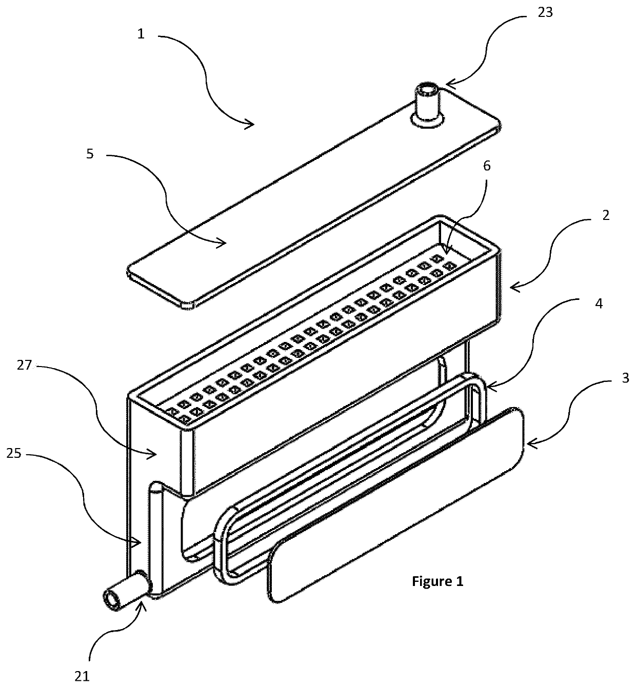
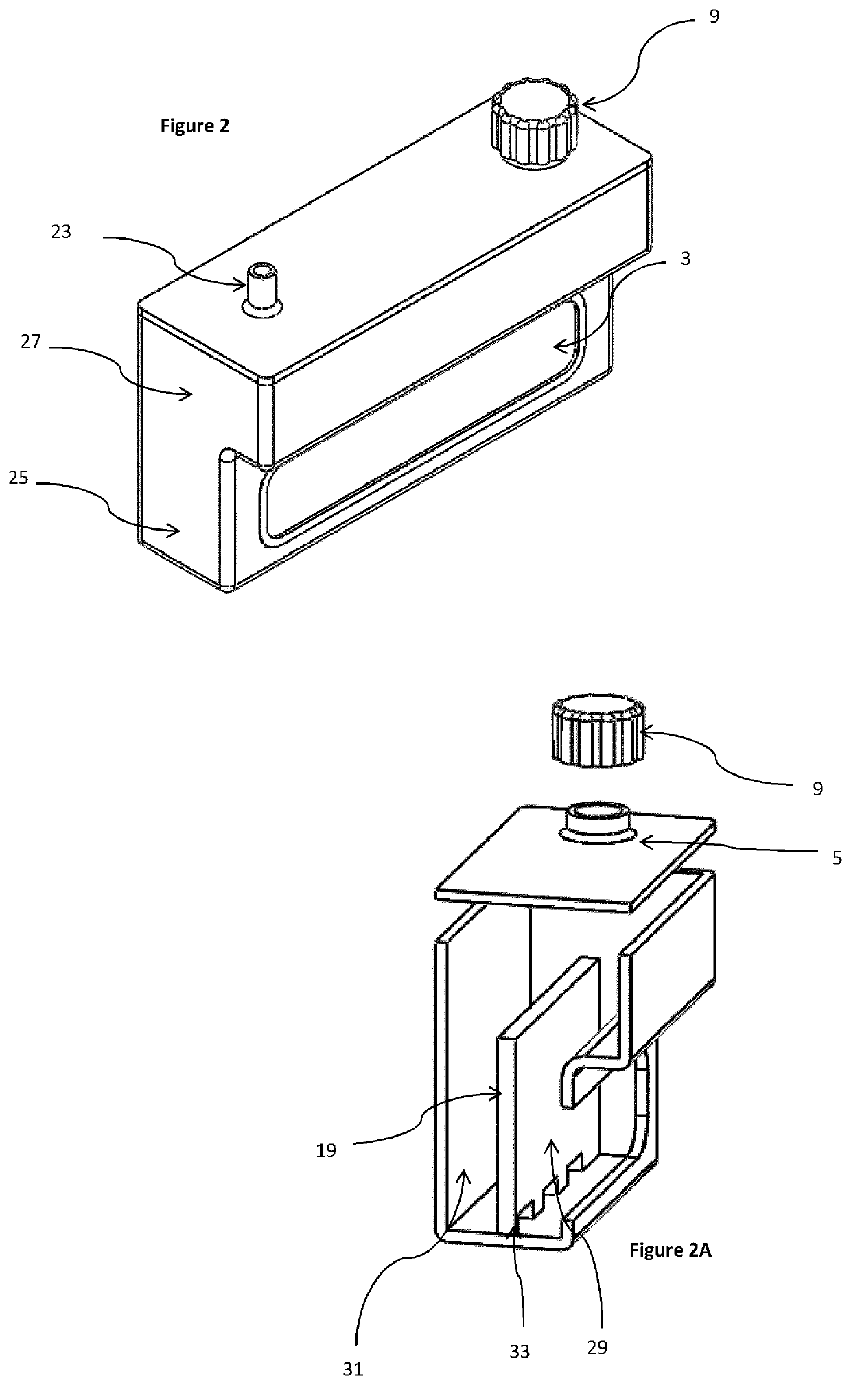
[0024]In the following description, functionally similar parts carry the same reference numerals between figures. Embodiments of the invention are now described, by way of example only, with reference to the accompanying drawings. In this description ‘upper’, ‘lower’, ‘top’, bottom’ and similar terms are defined with reference to the normal orientation of the steam generator 1 when it is in use, for instance with the steam output 23 located toward the top of the steam generator 1 to allow steam to escape through it.

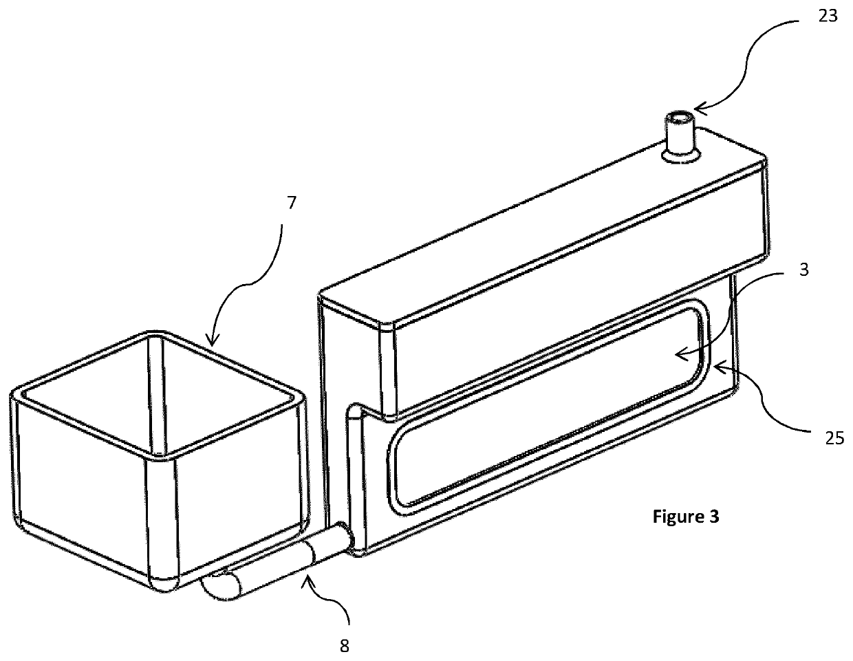
[0025]Embodiments of the invention comprise a steam generator 1 with an electrical heating element 3 mounted in an upright orientation with respect to the orientation of the steam generator 1 in use, where upright includes vertical and substantially vertical orientations. The steam generator 1 may be a modular unit within a larger appliance, or may be a standalone steam generator 1.

[0026]The steam generators 1 of embodiments of the present invention include a heating cham...


PUM


Abstract

A steam generator including a heating chamber for heating water to generate steam, with a sidewall of the heating chamber being a heating element. The steam generator may be installed in an appliance, and may be removably installed in the appliance.

Description

FIELD OF THE INVENTION[0001]The present invention relates to a steam generator, and particularly to a steam generator for use in domestic applications.BACKGROUND OF THE INVENTION[0002]Steam is used in many different fields of application and for a wide range of purposes. For instance, in the domestic environment steam is used to assist in cleaning, practical DIY tasks, cooking and ironing. Accordingly, steam generators are found in many domestic appliances, such as clothes irons, steam cleaners, wallpaper strippers, and cooking ovens. However, in domestic applications in particular, there are a number of particularly important concerns for users.[0003]One such concern is the overall size of an appliance, with small and compact appliances being highly desirable. Accordingly, space is at a premium for designers of such appliances, as they seek to make appliances as small as possible. In current steam appliances, the steam generator unit is a limiting feature which dictates the minimum...

Claims


Application Information

Patent Timeline
IPC IPC(8): F22B1/28D06F75/10H05B3/20F22B37/30
CPCF22B1/285D06F75/10H05B2203/021F22B37/30H05B2203/013H05B3/20F22B1/284D06F58/203D06F75/12D06F75/14D06F73/00D06F39/40D06F75/16F22B1/00
Inventor WONG, KWOK HUNGNIJHOFF, ALEX REINIERHUNT, ANDREW
Owner OTTER CONTROLS LTD
Why Eureka
Try Eureka