Eureka AIR delivers breakthrough ideas for toughest innovation challenges, trusted by R&D personnel around the world.

Imaging sensor air shield

a sensor and air shield technology, applied in the field of sensor units, can solve the problems of preventing the functioning of the lens or other surface affecting the performance damage to the components of the detection device, so as to prevent or mitigate the damage caused by the impact

Pending Publication Date: 2022-06-16
CONTINENTAL AUTONOMOUS MOBILITY US LLC
View PDF11 Cites 0 Cited by
  • Summary
  • Abstract
  • Description
  • Claims
  • Application Information

AI Technical Summary

Benefits of technology

The present invention is a detection device that uses a system to deliver pressurized fluid or compressed air to its lens or optical surface to prevent or mitigate damage caused by the impact of debris. The detection device uses its own image detection function to track the trajectory of an object that might strike and impact the detection device. The sensor activates a high pressure burst of pressurized fluid or compressed air to shield or mitigate against damage from impact. The technical effect of this invention is to provide a reliable and effective measure to prevent damage to detection devices, even in cases where they may be impacted by debris.

Problems solved by technology

These types of detection devices may have various lenses or other surfaces which may accumulate debris during travel of the vehicle, or may be impacted by objects such as rocks, ice, or the like, which have the potential to damage the components of the detection device.
A rock or piece of ice impacting the lens or other surface may cause damage in the form of a crack, chip, or scratch, such that the lens or other surface of the detection device may be prevented from functioning properly, and prevented from detecting objects around the vehicle.

Method used


Image

  • Imaging sensor air shield
  • Imaging sensor air shield

Examples


Embodiment Construction

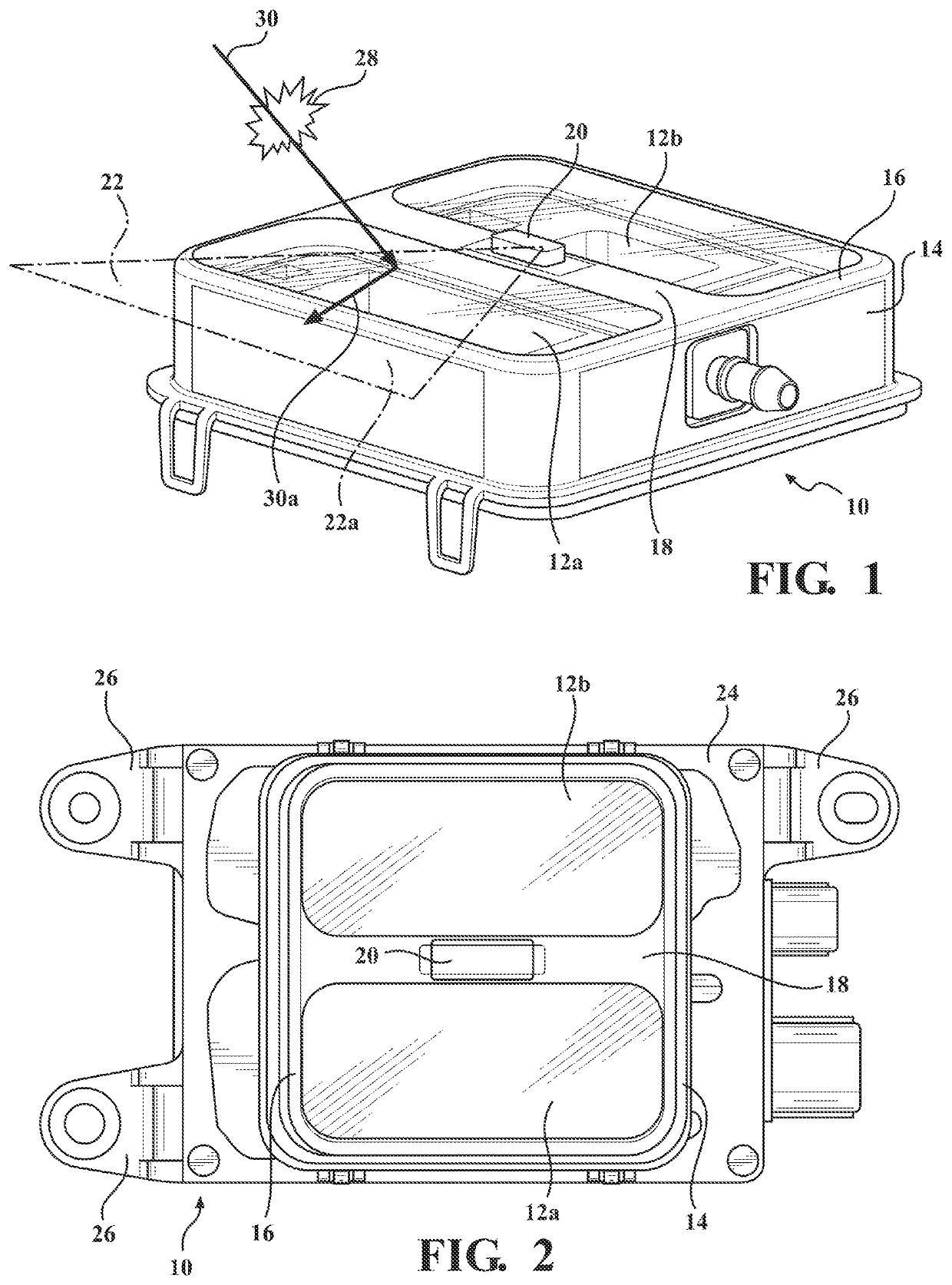
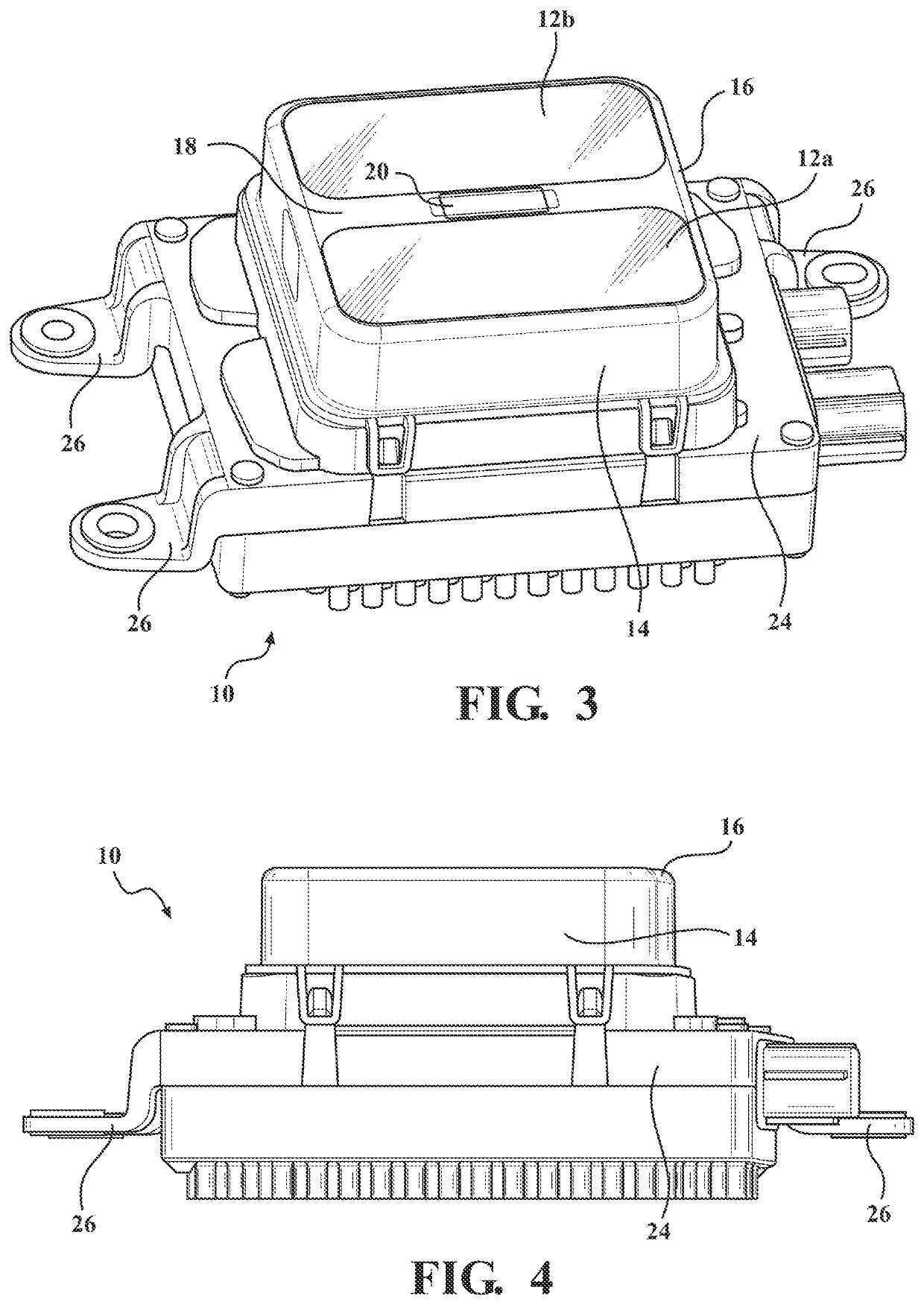
[0019]The following description of the preferred embodiment(s) is merely exemplary in nature and is in no way intended to limit the invention, its application, or uses.

[0020]A detection device having a shielding function is shown in the Figures generally at 10. The detection device 10 has at least one surface, and in the embodiment shown has multiple surfaces 12a,12b, and in this embodiment, each surface 12a,12b is a type of optical surface or a lens of a sensor. However, it is within the scope of the invention that the detection device 10 may be any type of detection device, such as a sensor, radar, LIDAR, camera, or the like. The lenses 12a,12b are mounted to a housing 14. Disposed in the housing 14 are various components used as part of the sensor. The housing 14 also includes an outer frame portion 16, and the outer frame portion 16 includes a central frame member 18.

[0021]Mounted to the central frame member 18 is a spray device 20. The spray device 20 may be a type of nozzle, o...


PUM


Abstract

A detection device is equipped with a system to deliver pressurized fluid or compressed air or both to a lens or other optical surface to prevent or mitigate damage caused by the impact of debris. The detection device uses its own image detection function to track the trajectory of an object that might strike and impact the detection device. The detection device activates a burst of pressurized fluid or compressed air or both to shield or mitigate damage from impact. The detection device includes a housing, at least one surface mounted to the housing, and a spray device mounted to the housing. A medium, such as a liquid, gas, or compressed air, is selectively sprayed by the spray device. The spray device is activated to spray the medium when an object is approaching the surface, such that the trajectory of the object is altered when the object contacts the medium.

Description

FIELD OF THE INVENTION[0001]The invention relates generally to a sensor unit which is equipped with a shielding function, where the sensor unit uses an image detection function to detect the trajectory of an object that may strike the sensor, and the sensor unit activates a burst of pressurized fluid or compressed air to act as a shield or mitigate damage from the impact of the object contacting the sensor unit.BACKGROUND OF THE INVENTION[0002]As vehicles have become more advanced, an increased number of features have been implemented to detect objects around a vehicle. Autonomous driving vehicles and vehicles having various driving assist functions incorporate the use of various detection devices, such as sensors, radars, and the like.[0003]These types of detection devices may have various lenses or other surfaces which may accumulate debris during travel of the vehicle, or may be impacted by objects such as rocks, ice, or the like, which have the potential to damage the components...

Claims


Application Information

Patent Timeline
Patent Type & Authority Applications(United States)
IPC IPC(8): G01S13/931G01S7/40
CPCG01S13/931G01S2007/4043G01S7/4004G01S7/4043G01S7/027B60S1/56
Inventor VRANJES, PAUL
Owner CONTINENTAL AUTONOMOUS MOBILITY US LLC
Why Eureka
Eureka Blog
Learn More