Eureka AIR delivers breakthrough ideas for toughest innovation challenges, trusted by R&D personnel around the world.

Sputtering apparatus and method thereof

a technology of sputtering apparatus and thin film, which is applied in the direction of electrolysis components, vacuum evaporation coatings, coatings, etc., can solve problems such as damage to the thin film to be formed, and achieve the effect of preventing or reducing damage to the thin film

Active Publication Date: 2015-12-31
SAMSUNG ELECTRONICS CO LTD
View PDF5 Cites 1 Cited by
  • Summary
  • Abstract
  • Description
  • Claims
  • Application Information

AI Technical Summary

Benefits of technology

The patent text describes a way to make thin films using a sputtering method without getting damage to the film from a by-product. This can be useful for making certain types of thin films.

Problems solved by technology

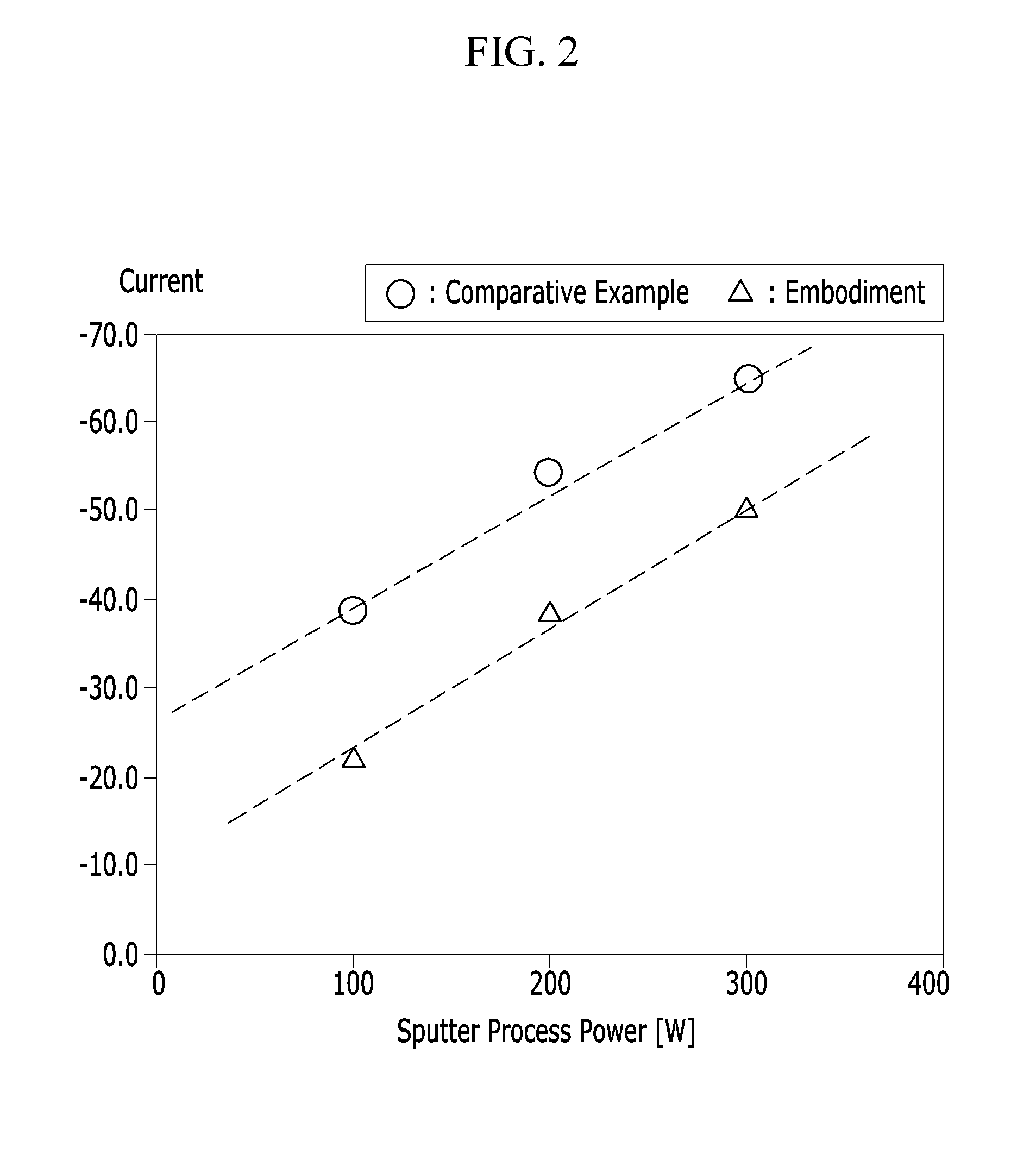
The emitted ions and / or electrons collide with a substrate thereby causing problems such as damage to the thin film to be formed or other thin films previously formed on the substrate.

Method used


Image

  • Sputtering apparatus and method thereof
  • Sputtering apparatus and method thereof
  • Sputtering apparatus and method thereof

Examples


Embodiment Construction

[0020]Various example embodiments will be described more fully hereinafter with reference to the accompanying drawings, in which some example embodiments are shown. As those skilled in the art would realize, the described example embodiments may be modified in various different ways, all without departing from the spirit or scope of example embodiments. Rather, these example embodiments are merely provided so that this disclosure will be thorough and complete, and will fully convey the scope of example embodiments to those skilled in the art. In the drawings, the sizes and relative sizes of the various layers and regions may have been exaggerated for clarity. Like numerals refer to like elements throughout.

[0021]It will be understood that when an element or layer is referred to as being “on,”“connected to” or “coupled to” another element or layer, it can be directly on, connected or coupled to the other element or layer or intervening elements or layers may be present. In contrast, ...


PUM

PropertyMeasurementUnit
relative dielectric constantaaaaaaaaaa
thicknessaaaaaaaaaa
thicknessaaaaaaaaaa

Abstract

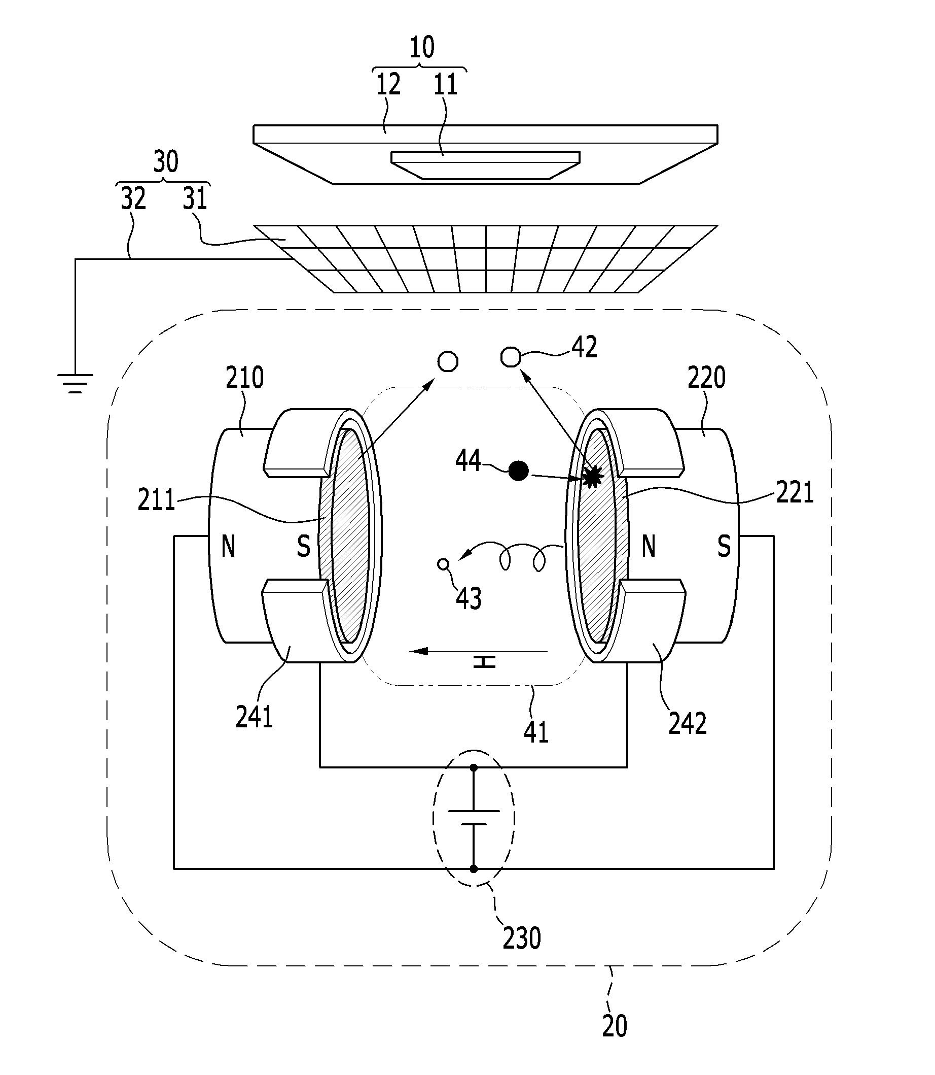
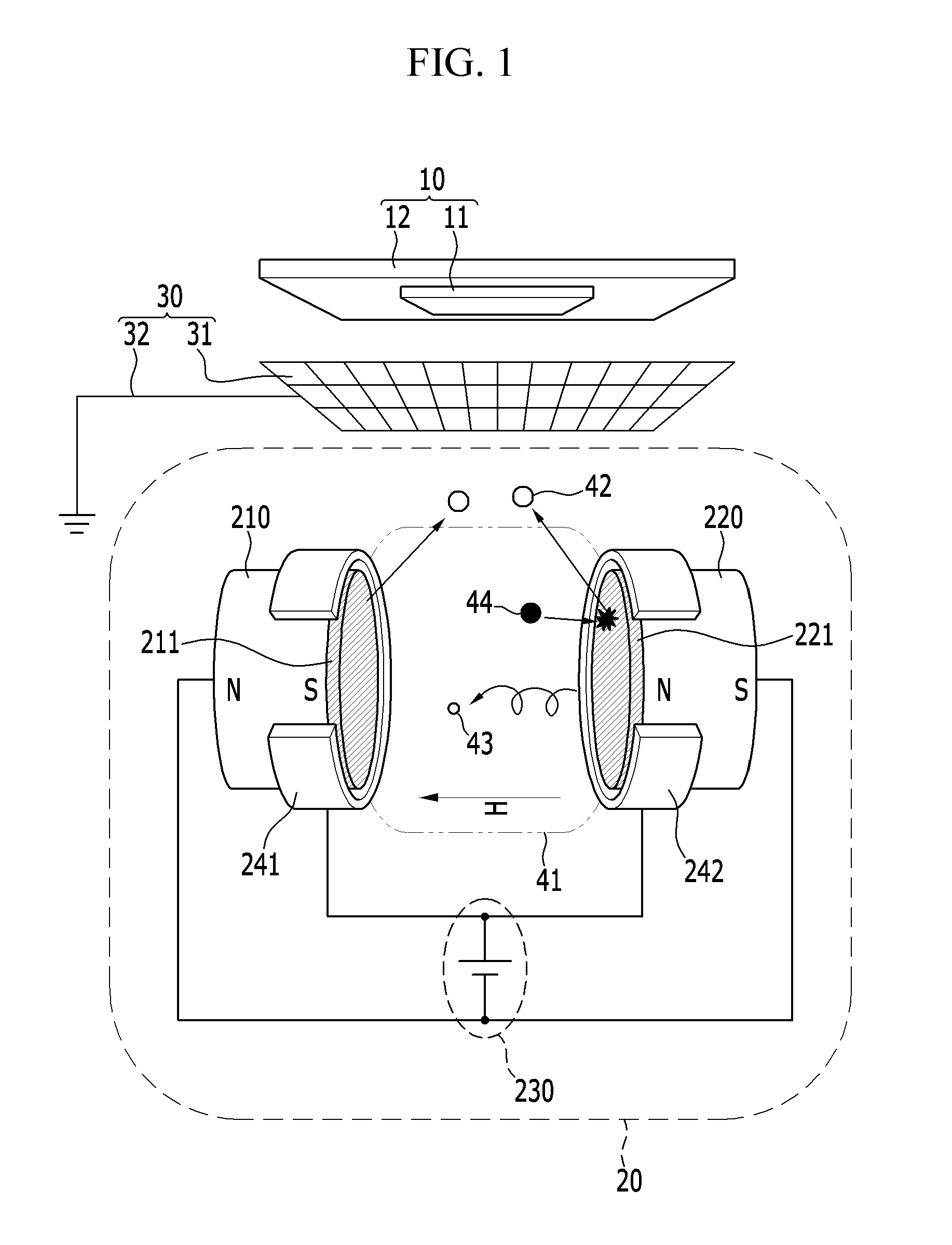
A method of forming a layer including disposing a first target and a second target to face each other with a first space therebetween, disposing a substrate to face the first space, generating plasma between the first target and the second target to perform sputtering on the substrate, disposing a capture net between the substrate and the the first space, and capturing anions and / or electrons that propagate toward the substrate from the first space.

Description

CROSS-REFERENCE TO RELATED APPLICATIONS[0001]This U.S. non-provisional patent application claims priority under 35 U.S.C. §119 to Korean Patent Application No. 10-2014-0080571, filed on Jun. 30, 2014, in the Korean Intellectual Property Office, the entire contents of which are incorporated herein by reference.BACKGROUND[0002]1. Field[0003]This disclosure relates to sputtering apparatuses and / or methods for forming a thin film.[0004]2. Description of the Related Art[0005]In order to fabricate a semiconductor, or a display device, thin films may be formed and patterned. Forming a high quality thin film having substantially no or a relatively low level of damage is desirable to form a fine pattern by patterning the thin film. The thin film may be formed by various methods such as chemical vapor deposition (CVD), atomic layer deposition, and sputtering depending upon material of thin film or an objective of forming the thin film. The sputtering is one of evaporation technique, and gener...

Claims


Application Information

Patent Timeline
Patent Type & Authority Applications(United States)
IPC IPC(8): C23C14/35C23C14/08C23C14/34H01J37/34
CPCC23C14/352H01J37/3417H01J37/3405H01J37/3467H01J37/3438C23C14/086C23C14/0068C23C14/225H01J37/3447
Inventor RYUICHI, SATOHKIM, KYU SIK
Owner SAMSUNG ELECTRONICS CO LTD
Why Eureka
Eureka Blog
Learn More