Method and system for transmitting and receiving an electromagnetic radiation beam with detection of orbital angular momentum and related telecommunication method and system

Pending Publication Date: 2022-06-16
UNIV DELGI STUDI DI MILANO
View PDF2 Cites 0 Cited by
  • Summary
  • Abstract
  • Description
  • Claims
  • Application Information

AI Technical Summary

Problems solved by technology

The “orbital angular momentum” variable, due to the features thereof mentioned above, is particularly difficult to be detected and characterized when the detector is illuminated only by a limited portion of the radiation beam, even if very distant from the singularity.
In fact, there are no reliable systems and methods allowing to detect the orbital angular momentum of an electromagnetic beam, for example, a laser, received by

Method used


Image

  • Method and system for transmitting and receiving an electromagnetic radiation beam with detection of orbital angular momentum and related telecommunication method and system
  • Method and system for transmitting and receiving an electromagnetic radiation beam with detection of orbital angular momentum and related telecommunication method and system
  • Method and system for transmitting and receiving an electromagnetic radiation beam with detection of orbital angular momentum and related telecommunication method and system

Examples


Embodiment Construction

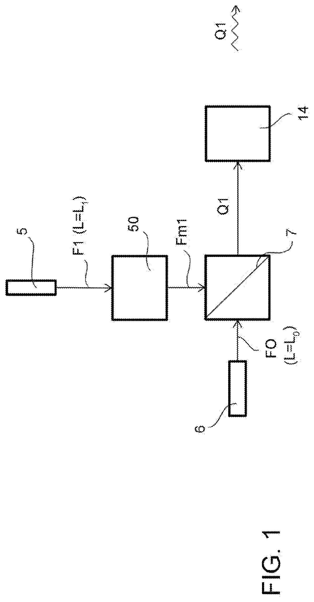
[0027]With reference to FIGS. 1 to 6, a method for transmitting and receiving an electromagnetic radiation beam is described, adapted to determine an orbital angular momentum of the received electromagnetic radiation beam.

[0028]The method, first of all, comprises the steps of generating at least one main electromagnetic radiation beam F1 characterized by a first orbital angular momentum L1, by a first spectrum in a first frequency band, and by a first beam radius of curvature, and of generating a reference electromagnetic radiation beam F0, characterized by a second orbital angular momentum L0, by a second spectrum in a second frequency band which is distinct from the aforesaid first frequency band, and by a second beam radius of curvature substantially coinciding with the aforesaid first beam radius of curvature.

[0029]It should be noted that the aforesaid characterization based on a first L1 and a second orbital angular momentum L0 may be correspondingly described also in terms of ...


PUM


Abstract

A method for transmitting and receiving an electromagnetic radiation beam, adapted to determine an orbital angular momentum of the received electromagnetic radiation beam, is described. There is further described a system for transmitting and receiving an electromagnetic radiation beam, capable of performing the aforesaid method. A method for performing a telecommunication of signals modulated according to any modulation technique and grouped by means of orbital angular momentum multiplexing is further described. There is further described a telecommunication system capable of performing the aforesaid method for performing a telecommunication of modulated signals.

Description


Claims


Application Information

Patent Timeline
Owner UNIV DELGI STUDI DI MILANO
Why Eureka
Try Eureka