
Wind-powered generator

a generator and wind power technology, applied in the direction of machines/engines, mechanical energy handling, mechanical equipment, etc., can solve the problems of limited or even non-existent green energy energy sources of energy producers, limiting the ability of many consumers to capitalize on available, green energy sources, etc., to reduce skin friction

Active Publication Date: 2022-06-23
PAPINI DAVID
View PDF4 Cites 0 Cited by
  • Summary
  • Abstract
  • Description
  • Claims
  • Application Information

AI Technical Summary

Benefits of technology

The patent describes a wind-powered generator that can be easily moved to different locations. It is protected from damage by an external housing and includes a coating to reduce friction. This allows for longer periods of use without maintenance and adds to the efficiency and reliability of wind power. The generator can be easily disassembled and remounted, making it ideal for use in motorhomes and RVs. Overall, the patent introduces a new technology that expands the use of wind power.

Problems solved by technology

While many consumers would like to contribute to the global effort by utilizing green energy, not all consumers have the ability to do so.
For example, depending a consumer's location, energy producers utilizing green energy may be limited or even non-existent.
Further, initial investment in green energy sources / generators can be high, thus discouraging energy producers from stepping into the market, and limiting many consumers ability to capitalize on the available, green energy sources.
Wind is one readily available power source and can be found in almost every location at most times. However, due to certain constraints (e.g., neighbor complaints, housing regulations, wildlife danger, etc.) consumers may be unable to even consider installation of a wind-powered generator.
Further, even in locations where wind-powered generators may be considered, based on certain aspects associated with various locations (e.g., wind shear, obstacles, etc.), wind airflow may be insufficient to generate stable power output using presently known wind turbines.
Therefore, despite many consumers' desire to derive power from wind, the proposition is often too costly and inefficient to be of interest.

Method used


Image

  • Wind-powered generator
  • Wind-powered generator
  • Wind-powered generator

Examples


Embodiment Construction

[0044]Reference will now be made in detail to the present exemplary embodiments of the disclosure, examples of which are illustrated in the accompanying drawings. Wherever possible, the same reference numbers will be used throughout the drawings to refer to the same or like parts.

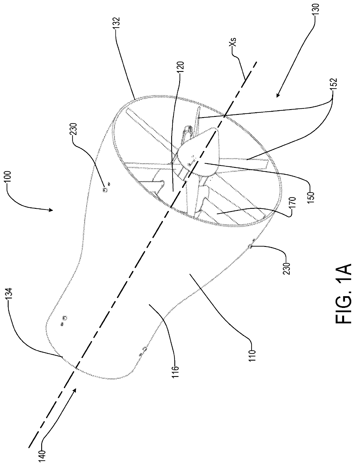
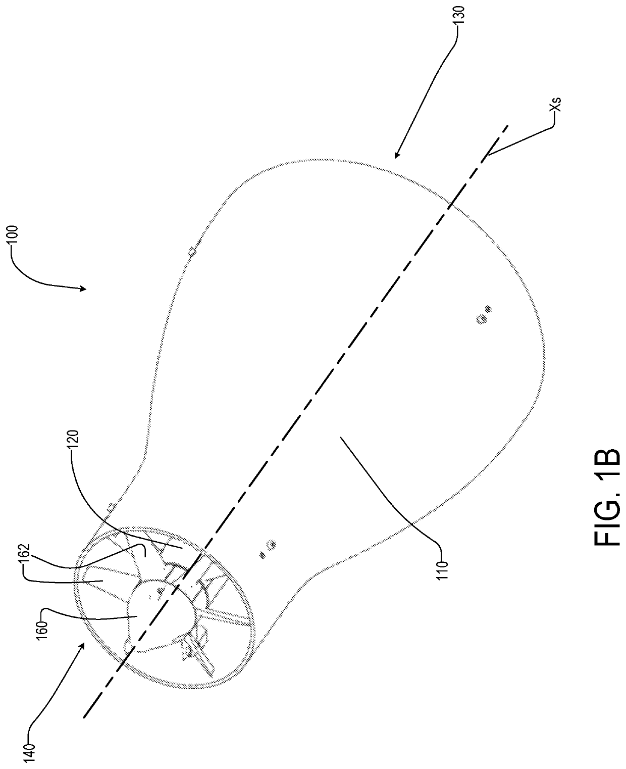
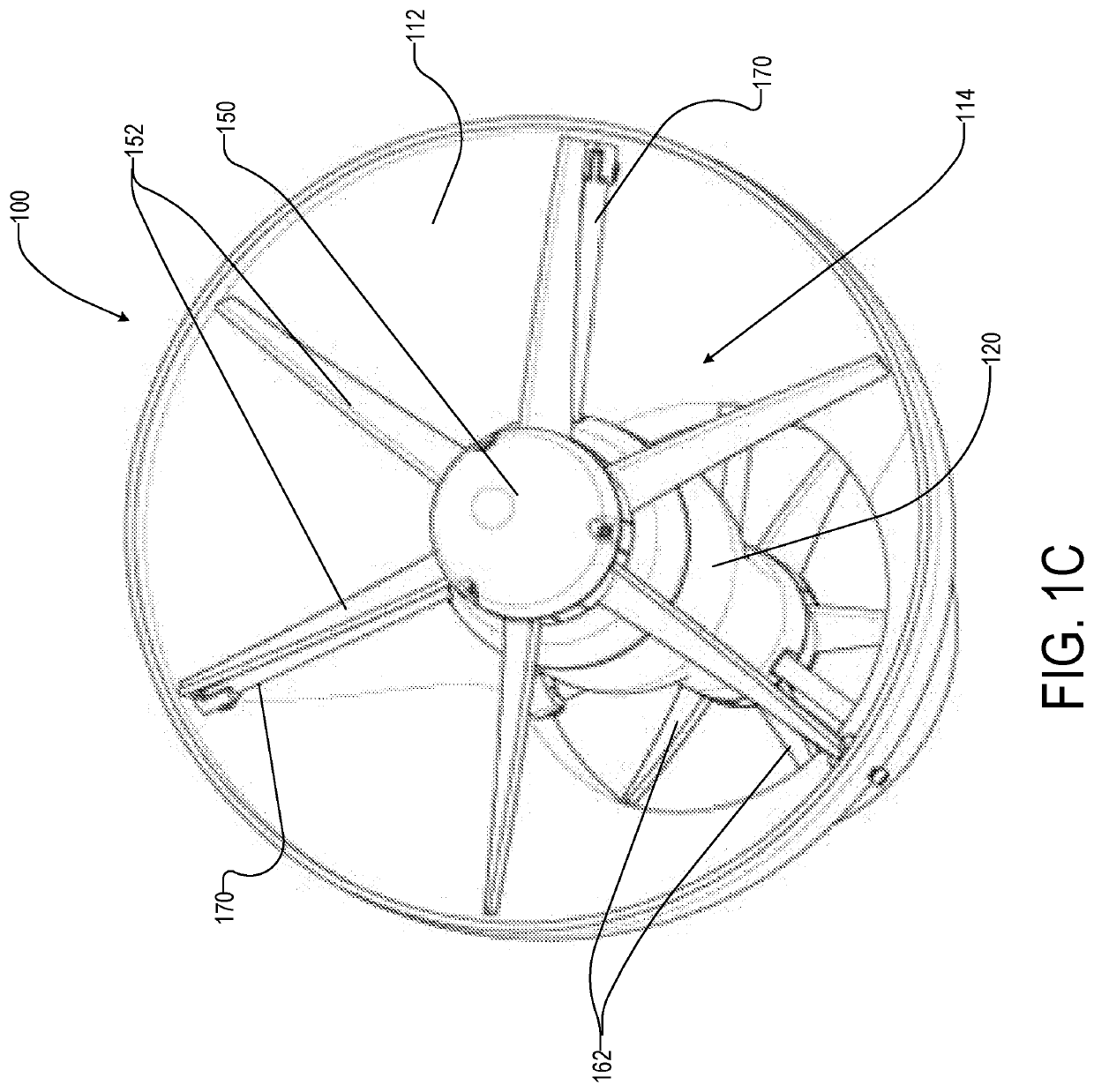
[0045]FIGS. 1A-1C are a perspective views of an illustrative wind-powered generator 100 according to embodiments of the present disclosure. Wind-powered generator 100 may include, for example, a housing 110, a nacelle 120, an inlet rotor 150, an outlet rotor 160, and supporting members 170, among others.

[0046]The housing 110 includes an inlet 130 configured to permit entry of wind into housing 110, and an outlet 140 configured to permit exit of the wind from housing 110. Wind entering inlet 130 impinges upon portions (e.g., rotor blades 152) of the inlet rotor 150 mounted on nacelle 120 to drive the inlet rotor 150 in rotation based on a blade pitch of the rotor blades 152 of inlet rotor 150. Similarly, win...


PUM


Abstract

A wind-powered generator is provided. The wind-powered generator includes a housing defining an internal volume and having an inlet, an outlet, and a throat, the inlet, outlet, and throat being coaxial about an axis of symmetry of the housing, wherein a portion of the internal volume between a leading edge of the housing and the throat is defined by revolution of a curve about the axis of symmetry, and the internal volume between the throat and a trailing edge of the outlet is defined by revolution of a substantially straight line about the axis of symmetry and a nacelle mounted within the internal volume. The nacelle includes a first rotor mounted on a first end of the nacelle and positioned at least partially within the inlet, the first rotor comprising a first output shaft configured to output a first power output, and a second rotor mounted on a second end of the nacelle opposite the first end, the second rotor being positioned at least partially within the outlet and having a diameter less than the first rotor, wherein the second rotor comprises a second output shaft configured to output a second power output. The first power output and the second power output are combined within an interior portion of the nacelle to provide a combined power output of the wind-powered generator, and a nacelle ratio between an outer diameter of the nacelle at the inlet to an outer diameter of the nacelle at the outlet ranges from between about 1.60-1.70 as measured, and a housing ratio of an inner diameter of the housing at the inlet to an inner diameter of the housing at the outlet ranges from about 1.85-1.97.

Description

CROSS-REFERENCE TO RELATED APPLICATIONS[0001]This application claims benefit of priority to U.S. Provisional Application No. 63 / 126,659 filed on Dec. 17, 2020, which is incorporated by reference in its entirety.FIELD OF THE DISCLOSURE[0002]The present disclosure relates to a wind-powered generator, and more particularly, to a wind-powered generator configured for use in residential and portable applications.BACKGROUND OF THE DISCLOSURE[0003]Green energy (e.g., solar, wind, hydro, etc.) has seen a rapid rise in importance during the past decade, due at least in part to a global consciousness regarding fossil fuel consumption and its impact on the environment. As more consumers have begun to feel a desire to do “their part” for ensuring a healthy environment, the demand for improved devices to enable such consumers to aid in the global effort has increased.[0004]While many consumers would like to contribute to the global effort by utilizing green energy, not all consumers have the abi...

Claims


Application Information

Patent Timeline
Patent Type & Authority Applications(United States)
IPC IPC(8): F03D1/04F03D9/25F03D80/80H02K5/20H02K7/18
CPCF03D1/04F03D9/25F05B2220/706H02K5/207H02K7/1838F03D80/82F03D1/025F05B2230/31F03D80/60F03D9/45Y02E10/72
Inventor PAPINI, DAVID
Owner PAPINI DAVID
Learn More