Display Driving Circuit and Frequency Correction Method of Display Driving Circuit
a display driving circuit and frequency correction technology, applied in static indicating devices, instruments, cathode-ray tube indicators, etc., can solve the problems of image quality degradation in the display device, inability to quickly solve the degradation of image quality, etc., and achieve the effect of quick correction of the frequency change of the oscillator clock signal
- Summary
- Abstract
- Description
- Claims
- Application Information
AI Technical Summary
Benefits of technology
Problems solved by technology
Method used
Image


Examples
Embodiment Construction
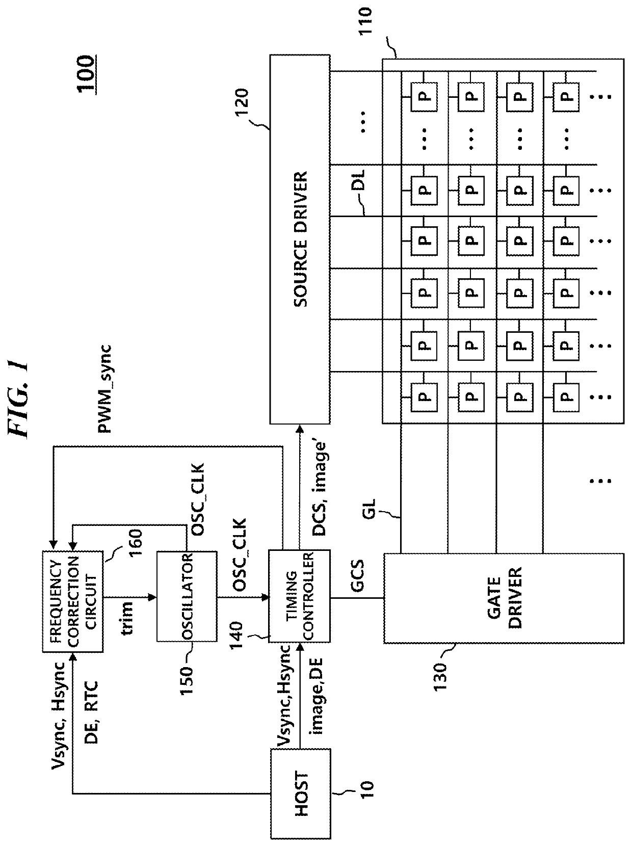
[0021]FIG. 1 is a configuration diagram of a display device in accordance with an embodiment.
[0022]Referring to FIG. 1, a display device 100 may include a display panel 110 and a display driving circuit which drives the display panel 110.
[0023]A plurality of data lines DL and a plurality of gate lines GL may be disposed in the display panel 110, and a plurality of pixels P may be disposed in the display panel 110. The plurality of pixels P may be disposed in a matrix shape formed by a plurality of rows and a plurality of columns.
[0024]The display driving circuit which drives the display panel 110 may include a source driver 120, a gate driver 130, a timing controller 140, an oscillator 150 and a frequency correction circuit 160.
[0025]In the display driving circuit, the gate driver 130 may output a scan signal of a turn-on voltage or a turn-off voltage to the gate line GL. When the scan signal of the turn-on voltage is supplied to a pixel P, the corresponding pixel P is connected to ...
PUM
 Abstract
Description
Claims
Application Information