Light-emitting display device

a technology of light-emitting display and display angle, which is applied in the direction of semiconductor devices, diodes, electrical devices, etc., can solve the problem of degrading the brightness of the display angle when the viewing angle is changed

Pending Publication Date: 2022-06-30
LG DISPLAY CO LTD
View PDF5 Cites 0 Cited by
  • Summary
  • Abstract
  • Description
  • Claims
  • Application Information

AI Technical Summary

Problems solved by technology

A light-emitting display device is designed using a principle in which light resonates between two opposing electrodes and is optimized for a fr...

Method used


Image

  • Light-emitting display device
  • Light-emitting display device
  • Light-emitting display device

Examples


first embodiment

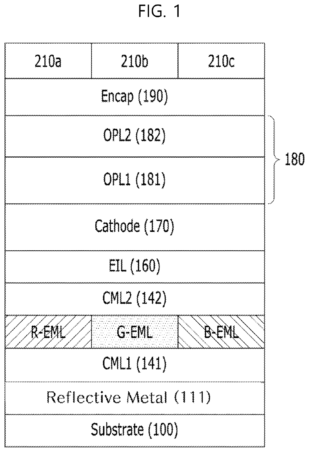
[0034]FIG. 1 is a cross-sectional view of a light-emitting display device according to the present disclosure. All the components of the display device according to all embodiments of the present invention are operatively coupled and configured.

[0035]As shown in FIG. 1, the light-emitting display device according to the first embodiment of the present disclosure can include a substrate 100 having a plurality of light-emitting units, light-emitting layers R-EML, G-EML, and B-EML included in a light-emitting unit, a reflective structure (or a reflective layer) 111 disposed between the light-emitting layers R-EML, G-EML, and B-EML and the substrate 100 in the light-emitting unit, a transmissive electrode (e.g., cathode) 170 positioned above the light-emitting layer over a plurality of pixels on the substrate, an optical compensation structure 180 that is in contact with the transmissive electrode 170 and has destructive interference characteristics, an encapsulation layer 190 on the op...

second embodiment

[0062]FIG. 3 is a cross-sectional view of a light-emitting display device according to the present disclosure. FIG. 4 is a cross-sectional view of a dielectric Bragg mirror of FIG. 3. FIGS. 5A and 5B are graphs showing the principle of a reflective mirror of a dielectric Bragg mirror and reflectivity thereof.

[0063]In the light-emitting display device of FIG. 3 according to the second embodiment of the present disclosure, a reflective structure 300 or a reflector of the light-emitting device can be configured separately from a first electrode 120.

[0064]Here, the reflective structure 300 can be formed as a metallic reflector but can also be formed of an insulating dielectric material, or a combination thereof.

[0065]When the reflective structure 300 is a metallic reflector, the reflective structure 300 can have a thickness of 100 nm or can satisfy a condition represented using Expression 3 below.

0.3<1-[(n-1)2+k2(n+1)2+k2]<0.03[Expression⁢⁢3]

Here, n is a refractive index and k is ...

third embodiment

[0070]FIG. 6 is a cross-sectional view of a light-emitting display device according to the present disclosure.

[0071]As shown in FIG. 6, the light-emitting display device according to the third embodiment of the present disclosure can be configured by applying different first to third reflective structures 310a, 310b, and 310c to a red light-emitting unit, a green light-emitting unit, and a blue light-emitting unit, respectively.

[0072]In this instance, the light-emitting display device can be designed using the same expression in such a way that the red light-emitting unit has wavelength peaks of 600 nm to 660 nm in FIGS. 3 and 5, the green light-emitting unit has wavelength peaks of 490 nm to 550 nm in FIGS. 3 and 5, and the blue light-emitting unit has wavelength peaks of 430 nm to 490 nm in FIGS. 3 and 5. However, because the wavelength peaks are different, the high refractive index layer and the low refractive index layer to be applied to the first to third reflective structures ...


PUM


Abstract

Discussed is a light-emitting display device, which emits light unchanged by maintaining a cavity of internal light using reverse cavity characteristics through an optical compensation structure, and achieves high luminance characteristics despite a change in a viewing angle, prevents external light from being reflected, and is excellent in terms of efficiency and lifespan by combining the optical compensation structure with a color filter structure. The optical compensation structure includes at least one first layer having a first refractive index and at least one second layer having a second refractive index greater than the first refractive index, the first layer being thicker than the second layer.

Description

CROSS-REFERENCE TO RELATED APPLICATIONS[0001]This application claims the priority benefit of Korean Patent Application No. 10-2020-0190035, filed in the Republic of Korea on Dec. 31, 2020, the entire contents of which are hereby expressly incorporated by reference as if fully set forth herein into the present application.BACKGROUND OF THE DISCLOSUREField of the Disclosure[0002]Embodiments of present disclosure relate to a display device, and more particularly to a light-emitting display device for preventing viewing angle from being changed depending on luminance and maintaining high luminance irrespective of the viewing angle by changing the configuration.Discussion of the Related Art[0003]Self-luminous display devices such as organic light-emitting displays or quantum dot light-emitting displays for compact and clear color display without a separate light source have been considered as a competitive application thereof.[0004]A self-luminous display device includes a plurality of p...

Claims


Application Information

Patent Timeline
IPC IPC(8): H01L51/52H01L27/32
CPCH01L51/5271H01L51/5237H01L51/5265H01L27/322H01L51/5218H01L51/5275H10K59/38H10K59/12H10K50/85H10K50/858H10K50/856H10K50/86H10K50/818H10K50/852H10K59/87H01L33/58H01L33/405H01L33/42H01L33/20H01L33/10H01L33/52H01L27/156H10K50/84
Inventor KIM, JAE HYEONKIM, KWAN SOOKIM, MIN JEEKIM, SEOK HYUNLIM, YOUNG NAMSONG, MIN GEUN
Owner LG DISPLAY CO LTD
Why Eureka
Try Eureka