
Acoustic device

a technology of acoustic devices and dampers, which is applied in the direction of transducer details, loudspeaker casing supports, electrical transducers, etc., can solve the problems of damper colliding with the damper regulation unit, difficult to completely prevent damage to the diaphragm, and deterioration of acoustic characteristics in the emitted sound frequency rang

Active Publication Date: 2022-06-30
ALPS ALPINE CO LTD
View PDF5 Cites 0 Cited by
  • Summary
  • Abstract
  • Description
  • Claims
  • Application Information

AI Technical Summary

Benefits of technology

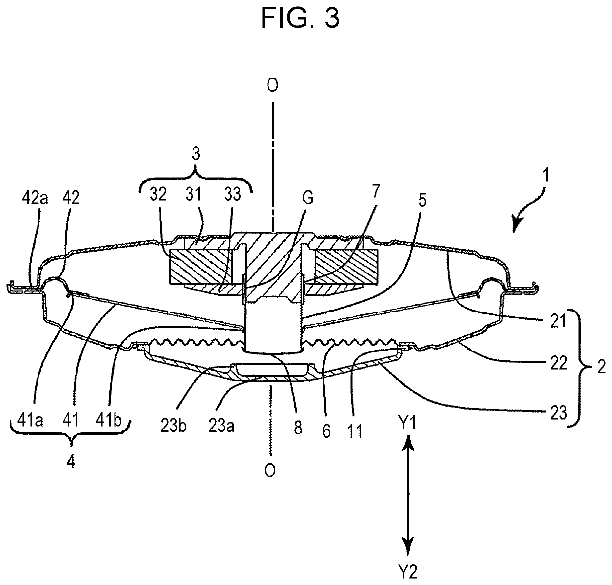
The present invention describes an acoustic device that can prevent damage to the diaphragm and maintain good acoustic quality even when the diaphragm moves with a large amplitude due to excessive input to the voice coil. The device has a configuration where a damper regulation unit is placed behind the damper to face it. When the vibrating body moves, the damper collides with the damper regulation unit and prevents damage to the vibrating body, which helps maintain good acoustic quality.

Problems solved by technology

However, since collision of the diaphragm does occur, it is difficult to completely prevent damage to the diaphragm.
If even a small area of damage occurs to the diaphragm, the acoustic characteristics in the emitted sound frequency range may deteriorate.
Therefore, when the vibrating body moves with a large amplitude due to an excessive input to the voice coil, the damper collides with the damper regulation unit.

Method used


Image

  • Acoustic device
  • Acoustic device
  • Acoustic device

Examples


Embodiment Construction

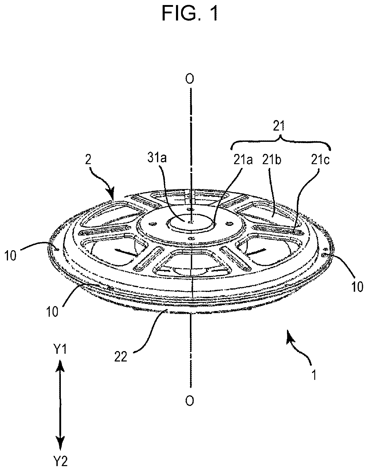
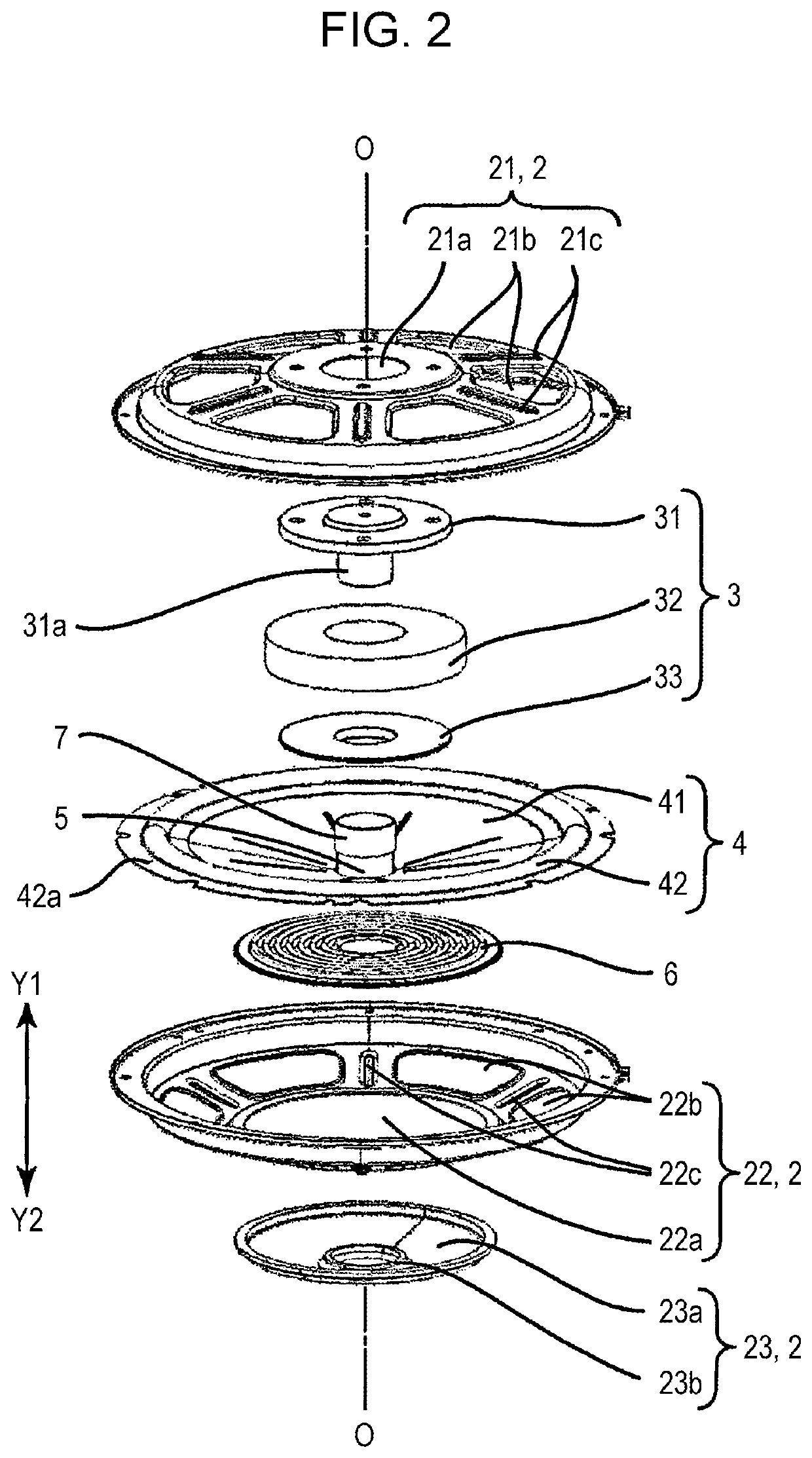
[0019]An acoustic device 1 according to an embodiment of the present invention is described with reference to FIGS. 1 to 4. In terms of the acoustic device 1, the Y1 direction is a forward direction that is a sound emitting direction, and the Y2 direction is a rearward direction that is opposite to the sound emitting direction. A center line O extending in the sound emitting direction is illustrated in FIGS. 1 to 4.

[0020]As illustrated in FIG. 1, the acoustic device 1 includes a main body case 2. As illustrated in FIG. 2, the main body case 2 includes a front case 21, a rear case 22, and a cover member 23. As illustrated in FIG. 1, the front case 21 and the rear case 22 are fastened to each other by screw fastening portions 10 provided at multiple locations in the outer circumferential portion of the front case 21 and the outer circumferential portion of the rear case 22. The front case 21 and the rear case 22 are formed by injection molding using a synthetic resin material or by di...


PUM


Abstract

An acoustic device includes a main body case, a vibrating body provided inside of the main body case, a magnetic circuit unit disposed in front of the vibrating body in a sound emitting direction of the vibrating body, a coil located inside of a magnetic gap of the magnetic circuit unit, a bobbin configured to support the coil and vibrate along with the vibrating body, and a damper configured to connect the main body case to the bobbin. The damper is disposed in the rear of the vibrating body, and a damper regulation unit is provided in the rear of the damper at a position facing the damper.

Description

RELATED APPLICATION[0001]The present application claims priority to Japanese Patent Application Number 2020-218513, filed Dec. 28, 2020, the entirety of which is hereby incorporated by reference.BACKGROUND1. Field of the Invention[0002]The present invention relates to an acoustic device having a magnetic circuit unit disposed in front of a vibrating body in a direction of sound emission.2. Description of the Related Art[0003]JP 2006-148447 A describes a loudspeaker system in which a magnetic circuit is disposed on the sound emitting side of a diaphragm in order to reduce the space required to mount a loudspeaker.[0004]In the loudspeaker system, a buffer member having a buffering function is provided near the lower end of the outer circumferential wall of the yoke or on the upper surface of a stepped portion of the diaphragm. Even if the diaphragm moves with a large amplitude, the diaphragm collides with the yoke facing the diaphragm via the buffer member and, thus, significant damag...

Claims


Application Information

Patent Timeline
Patent Type & Authority Applications(United States)
IPC IPC(8): H04R1/28H04R1/02H04R7/12
CPCH04R1/2873H04R7/12H04R1/026H04R9/043
Inventor ITO, RYO
Owner ALPS ALPINE CO LTD
Learn More