Fire wall and method for opening same

a technology of fire wall and fire wall, which is applied in the field of fire wall, can solve problems such as the dismantling of sealing blocks

Pending Publication Date: 2022-07-07
SN DETUDE & DE CONSTR DE MOTEURS DAVIATION S N E C M A
View PDF5 Cites 0 Cited by
  • Summary
  • Abstract
  • Description
  • Claims
  • Application Information

AI Technical Summary

Problems solved by technology

This arrangement had however the disadvantage of normally requiring the dismantling of the sealing blocks, to allow the extraction by passage through the firewall of even a single duct and / or cable for its inspection, its maintenance, its repair or its replacement.

Method used


Image

  • Fire wall and method for opening same
  • Fire wall and method for opening same
  • Fire wall and method for opening same

Examples


first embodiment

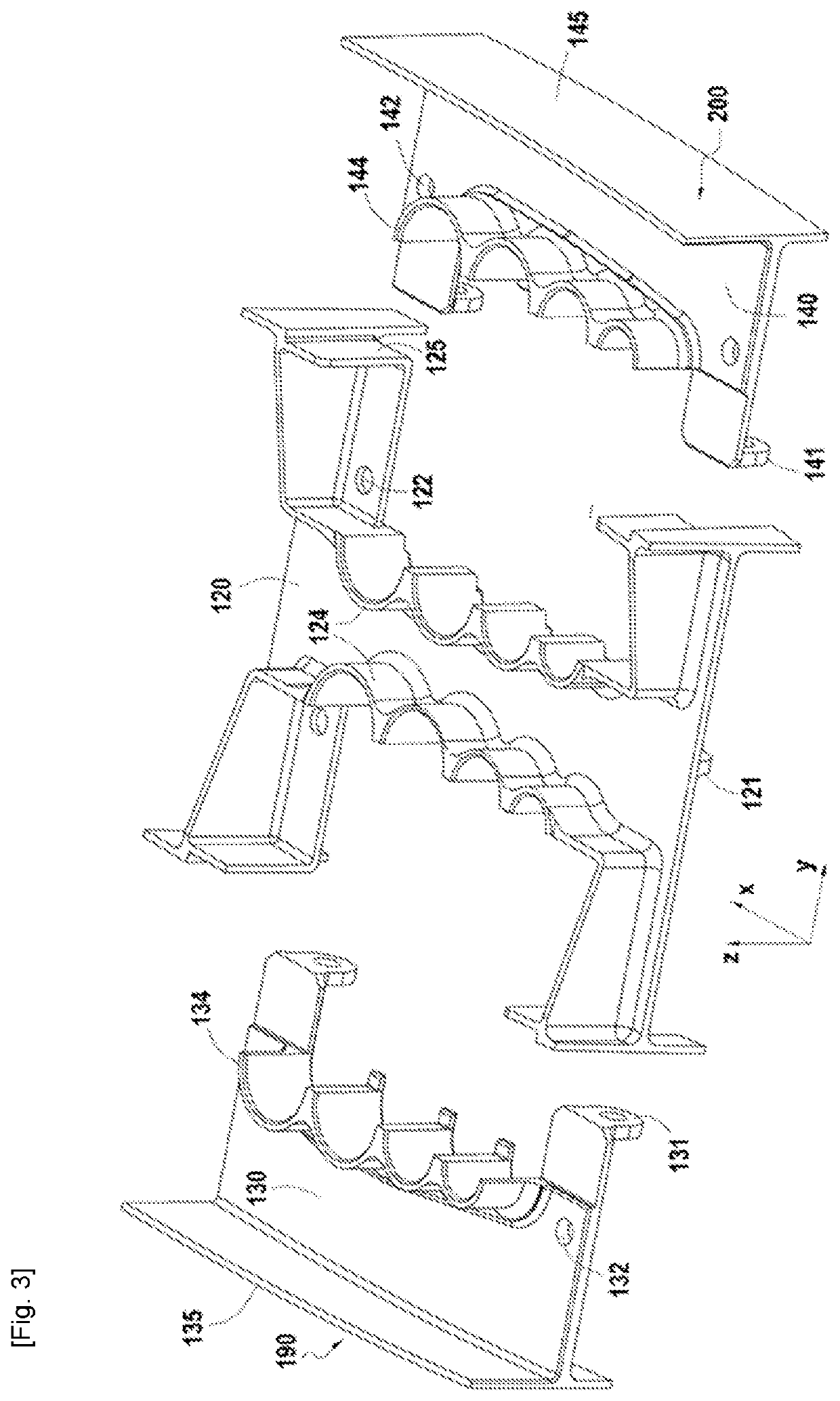
[0028]As illustrated in FIGS. 3, 4A and 4B, in at least a first embodiment, the firewall 112 can comprise a fixed portion 120 and two removable portions 130, 140. The fixed portion 120 can be integral with the tubular structure 108 of the auxiliary arm 105, while each of the removable portions 130, 140 can be releasably connected to the fixed portion 120 by bolts (not illustrated). At least one of these bolts can be oriented in the width direction Y of the firewall 112 to connect the jaws 121, 131, 141 protruding in the thickness direction Z of the firewall 112, respectively on the fixed portion 120, the first removable portion 130 and the second removable portion 140 of the firewall 112. Other bolts can be oriented in the the thickness direction Z of the firewall 112 to connect, respectively, the first removable portion 130 and the second removable portion 140 to the fixed portion 120. To allow the passage of these other bolts, the fixed portion 120 can have openings 122 aligned wi...

second embodiment

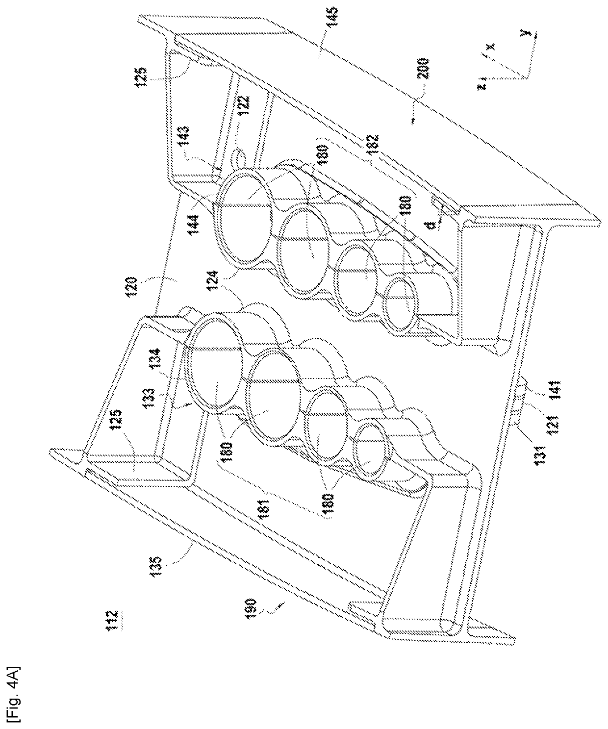
[0033]In the second embodiment, the first removable portion 130 can be individually dismantled to allow access to the ducts and / or the electrical cables 111 received in the first row 181 of through openings 180, in order to allow their individual inspection, maintenance, repair and or replacement, while the two removable portions 130, 140 can be dismantled to allow access to the ducts and / or the electrical cables 111 receive in the second row 182 of through openings 180, in order to allow their individual inspection, maintenance, repair and / or replacement.


PUM


Abstract

The invention relates to a firewall (112) for a turbomachine (100) auxiliary arm (106). This firewall (112), which has one or more through openings (180) in a thickness direction (Z) of the firewall (112), comprises a fixed portion (120) and a first removable portion (130) extending, in a width direction (Y), orthogonal to said thickness direction (Z), from at least one adjacent opening among the through openings (180), to a first outer edge (190) of the firewall (112). To open this firewall (112) in order to allow access to one or more ducts and/or electrical cables (111) received in the through openings (180), the first removable portion (130) can be dismantled.

Description

TECHNICAL FIELD[0001]The present disclosure relates to the field of turbomachines, and particularly a firewall for an auxiliary arm of a turbomachine.[0002]What is meant here by “turbomachine” is an assembly comprising, from upstream to downstream in a flow direction of a working fluid, a compressor, a combustion chamber, and a turbine connected mechanically by a rotating shaft to the compressor. Among turbomachines are therefore counted gas turbines, turbojets, turbofans, turboprops and turbine engines.PRIOR ART[0003]This disclosure relates in particular to turbofans, without however being limited to them. In fact, to allow the routing of fluids, such as fuel, lubricant or hydraulic fluid, as well as electricity, turbofans typically comprise auxiliary arms extending radially in the air stream of the fan, and receiving, within a tubular structure, bundles of ducts and / or electrical cables. One example of such auxiliary arms was disclosed in the publication of European patent applica...

Claims


Application Information

Patent Timeline
Patent Type & Authority Applications(United States)
IPC IPC(8): F02C7/25
CPCF02C7/25F05D2230/70F05D2230/60F05D2230/72
Inventor POU, ROMAIN HAROLD PATRICEDAUTREPPE, FRÉDÉRICDUFOUR, BERTRAND ROMAIN ADRIENGOUPIL, FRÉDÉRIC JACQUES EUGÈNE
Owner SN DETUDE & DE CONSTR DE MOTEURS DAVIATION S N E C M A
Why Eureka
Try Eureka