
Aspheric lens using e-value to control eye ball growth rate

Pending Publication Date: 2022-07-14
BRIGHTEN OPTIX CORP
View PDF0 Cites 0 Cited by
  • Summary
  • Abstract
  • Description
  • Claims
  • Application Information

AI Technical Summary

Benefits of technology

The present invention relates to an orthokeratology lens that can be used to correct nearsightedness or hyperopia. The lens has a specific design to control the growth rate of the eyeball and achieve optimal vision. The aspheric lens has a treatment zone and a positioning zone, which are designed to match the specific requirements of the cornea. The lens is simulated on the cornea using an electronic device, and a calculation formula is used to calculate the tear volume between the lens and the cornea. This allows for easy adjustment of the lens's eccentricity to match the tear volume required by the cornea shape, resulting in improved product yield. The technical effects of this innovation include the ability to correct nearsightedness or hyperopia through orthokeratology treatment, with a specific lens design that matches the requirements of the cornea. The lens is simulated on a virtual eye, adjusted to match the tear volume required, and manufactured to achieve optimal vision.

Problems solved by technology

However, although general orthokeratology lenses can correct myopia, some people cannot effectively control the progression of myopia by wearing orthokeratology lenses, so that the power of myopia will continue to increase.
Moreover, when the target power of the orthokeratology lens is low (between about −0.50 to −4.00 D), since the base curve of the orthokeratology lens is spherical, the space formed by the spherical base curve and the reverse curve on one side for the accumulation of tears will be insufficient, so that epithelial cells cannot be effectively squeezed, resulting in poor myopia control.

Method used


Image

  • Aspheric lens using e-value to control eye ball growth rate
  • Aspheric lens using e-value to control eye ball growth rate
  • Aspheric lens using e-value to control eye ball growth rate

Examples


Embodiment Construction

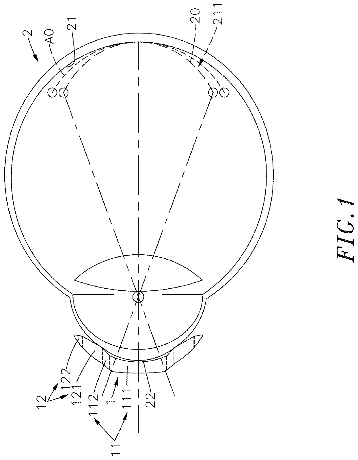
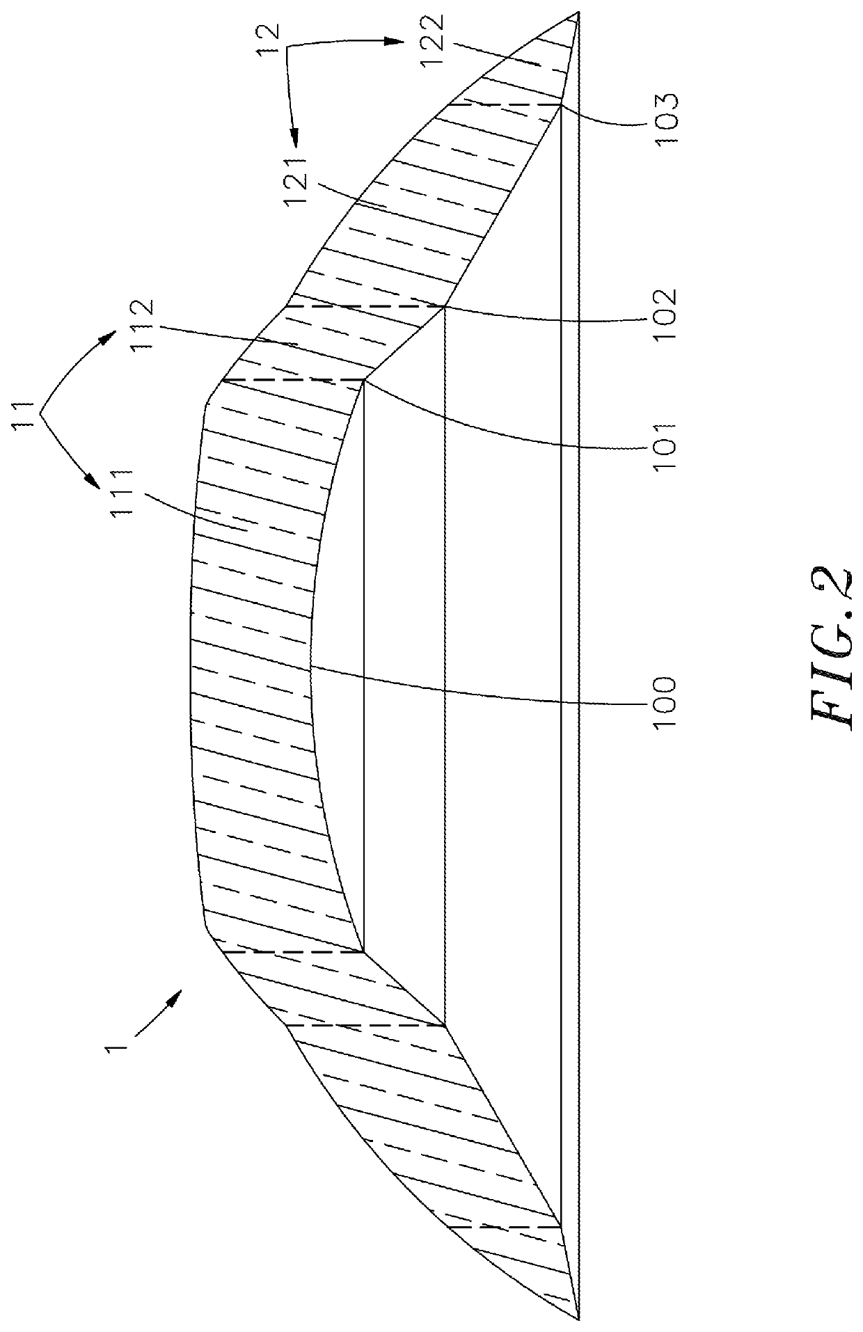
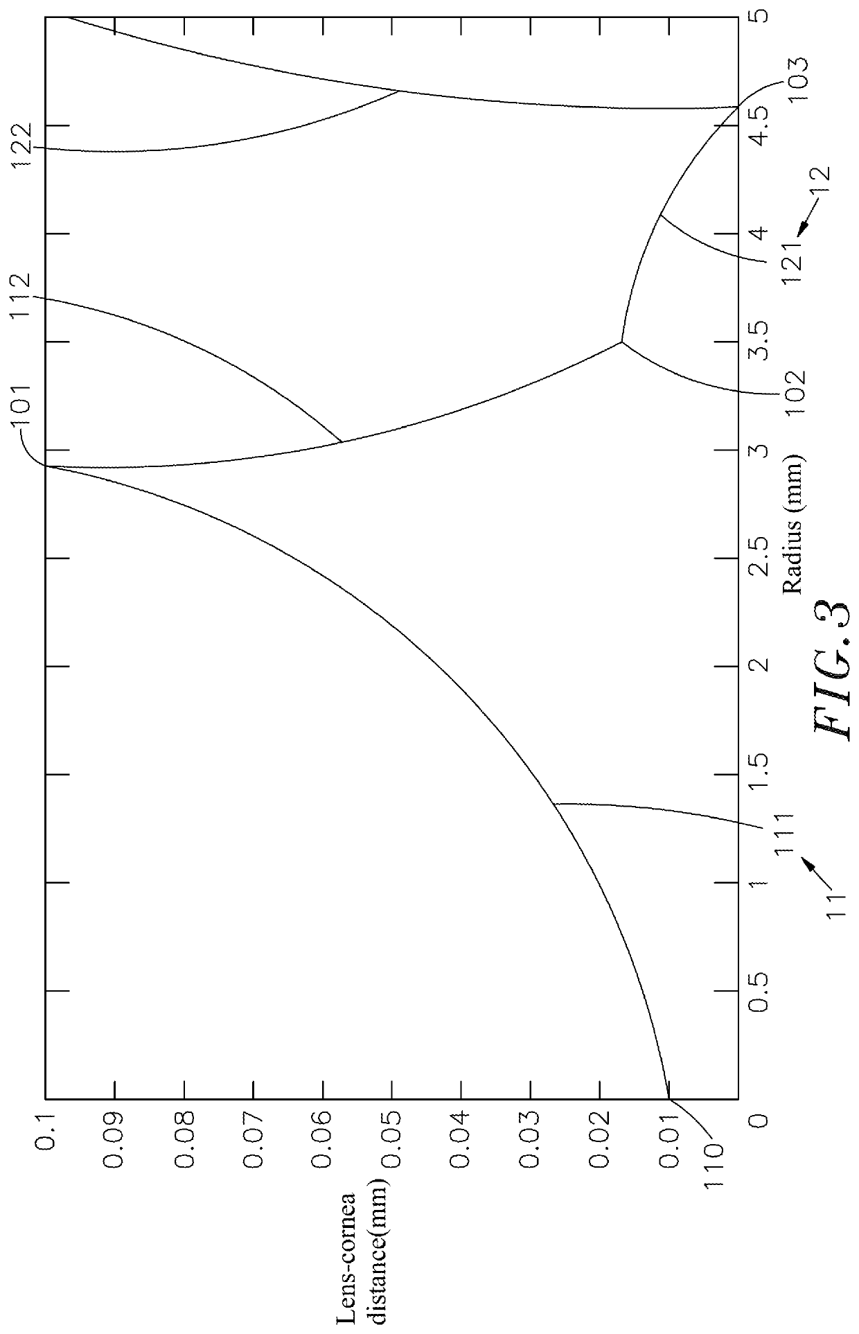
[0013]Referring to FIGS. 1, 2 and 3, as shown in the drawings, it can be clearly seen that the aspheric lens of the present invention uses E-value to control the eyeball growth rate. The lens 1 is an orthokeratology lens and the surface is aspheric. The lens 1 comprises a treatment zone 11 through which light passes to image at the retina 21 of the eyeball 2, and a positioning zone 12 of the non-visual area outside the treatment zone 11.

[0014]The treatment zone 11 comprises a base curve 111 (BC) whose eccentricity (E-value) can be between −4 and 4, and a reverse curve 112 (RC) formed on the outside of the base curve 111 to form a gap between the base curve 111 and the eyeball 2 for the accumulation of tears.

[0015]The positioning zone 12 comprises an alignment curve 121 that allows the lens 1 to be firmly fixed on the eyeball 2, and a peripheral curve 122 (PC) located outside the alignment curve 121.

[0016]The base curve 111 eccentricity of the treatment zone 11 of the lens 1 can be b...


PUM


Abstract

An aspheric lens includes a treatment zone through which light passes to image at the retina of eyeball and a positioning zone of non-visual area outside treatment zone. The treatment zone includes a base curve and a reverse curve formed on outside of base curve. The positioning zone includes an alignment curve and a peripheral curve located outside alignment curve. A center point is formed in center of base curve, the junction of base curve and reverse curve forms a first point of intersection, the junction of reverse curve and alignment curve forms a second point of intersection, and the junction of alignment curve and peripheral curve forms a third point of intersection. The linear distance between the center point and the cornea of the preset eyeball is between 9 μm˜21 μm. The linear distance between the first point of intersection and the cornea of the preset eyeball is between 89 μm˜189 μm.

Description

CROSS REFERENCE TO RELATED APPLICATIONS[0001]This application is a Continuation-In-Part of co-pending application Ser. No. 16 / 707,519, filed on Dec. 9, 2019, which is a Continuation-In-Part of application Ser. No. 16 / 158,833, filed on Oct. 12, 2018, for which priority is claimed under 35 U.S.C. § 120, the entire contents of which are hereby incorporated by reference.[0002]This application claims the priority benefit of Application No. 106217150 filed in Taiwan on Nov. 17, 2017.BACKGROUND OF THE INVENTION1. Field of the Invention[0003]The present invention relates to an aspheric lens using E-value to control eyeball growth rate, especially the treatment zone of the lens uses a base curve with an eccentricity between −4˜4 to make the eccentricity of the image shell on the retina non-zero, to increase the peripheral defocus area of the image on the retina, thereby effectively controlling myopia or hyperopia.2. Description of the Related Art[0004]At present, the main methods of correcti...

Claims


Application Information

Patent Timeline
IPC IPC(8): G02C7/04G02C7/06
CPCG02C7/047G02C7/061G02C2202/24G02C2202/12G02C7/041
Inventor WU, I-TSUNGLIN, WEN-PINLI, WEN-KAI
Owner BRIGHTEN OPTIX CORP
Learn More