Microchip electrophoresis method and microchip electrophoresis device

a microchip electrophoresis and electrophoresis technology, applied in the field of microchip electrophoresis methods and microchip electrophoresis devices, can solve problems such as the degradation of analysis performance, and achieve the effect of suppressing the decrease in analysis performan

Pending Publication Date: 2022-07-21
SHIMADZU CORP
View PDF0 Cites 0 Cited by
  • Summary
  • Abstract
  • Description
  • Claims
  • Application Information

AI Technical Summary

Benefits of technology

[0010]According to the present invention, it is possible to provide a microchip electrophoresis method and a microchip elect

Problems solved by technology

On the other hand, when the microchip is repeatedly used, the component contained in the sample of previous analysis or the component contained in a separatio

Method used


Image

  • Microchip electrophoresis method and microchip electrophoresis device
  • Microchip electrophoresis method and microchip electrophoresis device
  • Microchip electrophoresis method and microchip electrophoresis device

Examples


Embodiment Construction

[0029]With reference to the drawings, an embodiment of the present invention will be described in detail below. In the drawings, the same or corresponding portions are denoted by the same reference numeral, and the description will not be repeated in principle.

[0030][Configuration of Microchip Electrophoresis Device]

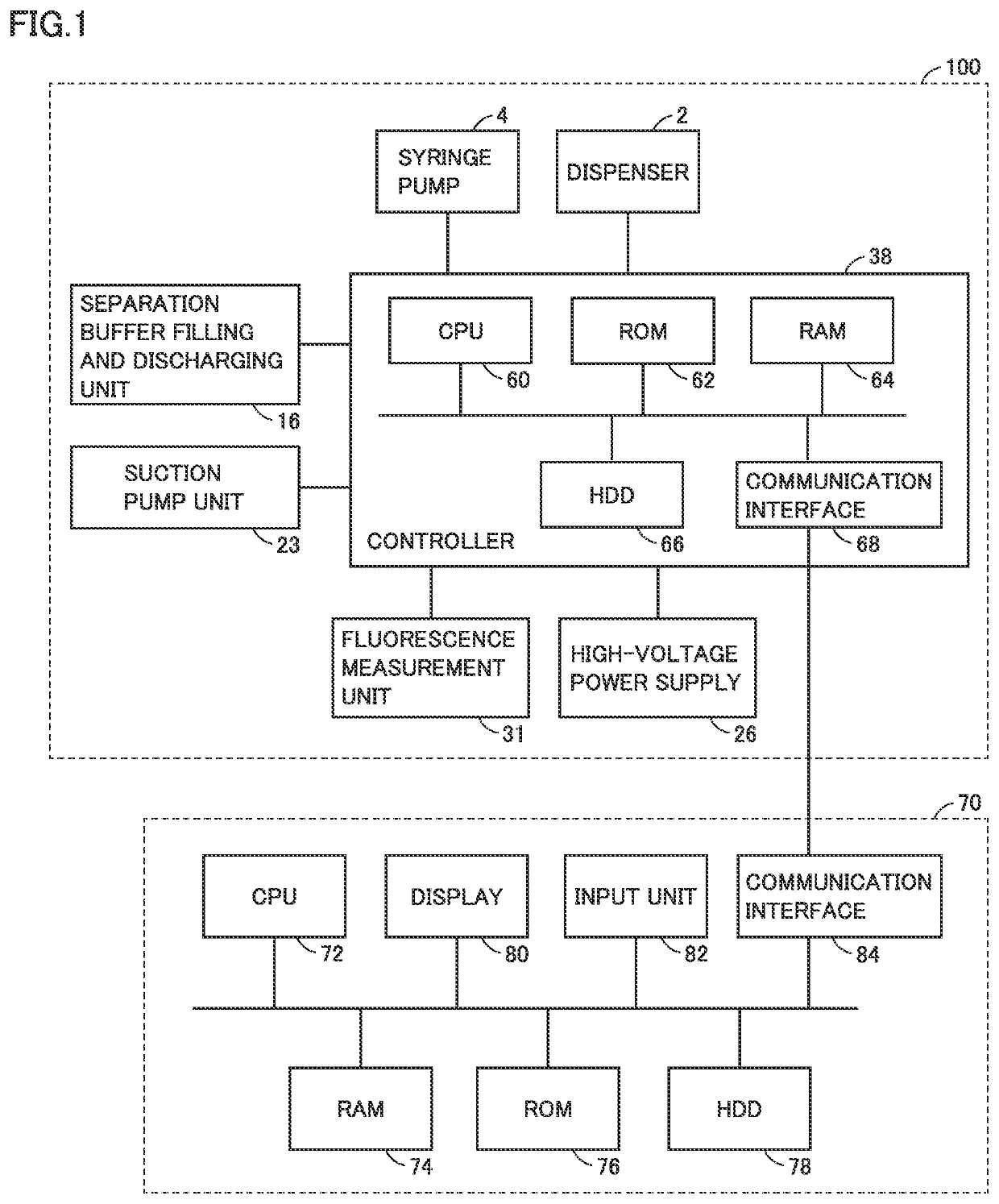
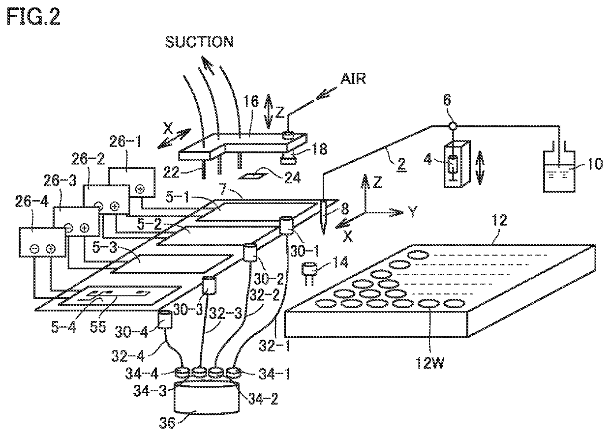
[0031]FIG. 1 is a view schematically illustrating an overall configuration of a microchip electrophoresis device 100 according to an embodiment of the present invention. FIG. 2 is a view schematically illustrating a configuration of a main part of microchip electrophoresis device 100 in FIG. 1.

[0032]Referring to FIG. 1, microchip electrophoresis device 100 includes a dispenser 2, a syringe pump 4, a separation buffer filling and discharging unit 16, a suction pump unit 23, a high-voltage power supply 26, a fluorescence measurement unit 31, and a controller 38. Microchip electrophoresis device 100 is communicably connected to a control device 70.

[0033]Referring to FIG. 2,...


PUM


Abstract

A microchip electrophoresis method includes sequentially analyzing a plurality of samples by repeating an analysis process by electrophoresis separation in a microchip, executing a cleaning process of the microchip, and setting timing of the cleaning process of the microchip at arbitrary timing between a plurality of analysis processes.

Description

TECHNICAL FIELD[0001]The present invention relates to a microchip electrophoresis method and a microchip electrophoresis device.BACKGROUND ART[0002]An electrophoresis device separates a trace sample at high speed by an electrophoresis method using a device such as a microchip or a capillary. For example, Japanese Patent Laying-Open No. 2012-251821 (PTL 1) discloses a microchip electrophoresis device. The microchip is configured by joining a base substrate in which a flow channel in which electrophoresis separation is executed and a flow channel in which a sample is introduced are formed and a base substrate on which a through-hole functioning as a reservoir for the sample and the separation medium is formed.[0003]In the microchip electrophoresis device described in PTL 1, analysis cost is reduced by repeatedly using the microchip. On the other hand, when the microchip is repeatedly used, the component contained in the sample of previous analysis or the component contained in a separ...

Claims


Application Information

Patent Timeline
IPC IPC(8): G01N27/447
CPCG01N27/44791G01N2550/00G01N37/00
Inventor KUMAGAI, HIDESATOARAI, AKIHIROHARADA, AKIRA
Owner SHIMADZU CORP
Why Eureka
Try Eureka