Fixing device, projection optical device, and projector

Pending Publication Date: 2022-07-21
SEIKO EPSON CORP
View PDF0 Cites 0 Cited by
  • Summary
  • Abstract
  • Description
  • Claims
  • Application Information

AI Technical Summary

Benefits of technology

The present invention is related to a fixing device, a projection optical device, and a projector. The fixing device fixes a lens barrel holding multiple lenses to a light emitting device, while the projection optical device includes the fixing device and the lenses. The fixing device includes a contact section and a pressing mechanism that press the holding section of the light emitting device when attached, while the projection optical device includes the fixing device and the lenses. The technical effect of the invention is improved attachment of a projection optical device to a light emitting device, ensuring stable and secure attachment of the lenses, and improved optical performance of the projection optical device.

Problems solved by technology

In the projection optical device, when an optical distance from a fixing section to the projector to an end portion on a light emission side of the projection optical device is long, it is likely that the positions of optical components move because of the influence of a bend due to the weight of the projection optical device or vibration from the outside and optical performance of the projection optical device is deteriorated.
Since the holding member needs to be accurately configured, manufacturing difficulty of the projection lens unit is high and manufacturing cost of the projection lens unit is also high.
In the projector described in Patent Literature 2, since it is necessary to separately provide the lens holding mechanism, it is troublesome to attach the lens holding mechanism to the projector.
For example, in a reverse placement posture in which the projector is placed vertically reversely from a normal placement posture, it is likely that the interchangeable lens cannot be held by the lens holding mechanism.

Method used


Image

  • Fixing device, projection optical device, and projector
  • Fixing device, projection optical device, and projector
  • Fixing device, projection optical device, and projector

Examples


Embodiment Construction

[0023]An embodiment of the present disclosure is explained below with reference to the drawings.

Schematic Configuration of a Projector

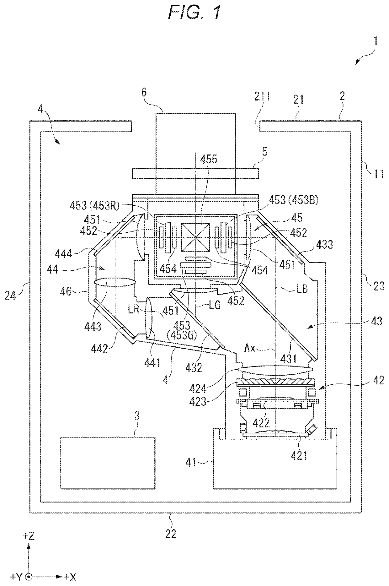
[0024]FIG. 1 is a schematic diagram showing the configuration of a projector 1 according to this embodiment.

[0025]The projector 1 according to this embodiment modulates, according to image information, light emitted from a light source 41 and enlarges and projects the modulated light onto a projection surface such as a screen. The projector 1 includes, as shown in FIG. 1, a light emitting device 11 and a projection optical device detachably attached to the light emitting device 11.

Configuration of the Light Emitting Device

[0026]The light emitting device 11 emits image light, which is light for forming an image. The light emitting device 11 includes an exterior housing 2, a control device 3, and an image generating device 4. Besides, the light emitting device 11 includes an attachment mechanism 5 (see FIG. 5) for attaching the projection optical device...


PUM


Abstract

A fixing device that fixes, to a light emitting device that emits light, a lens barrel included in a projection optical device and holding a plurality of lenses includes a first tube member, a contact section provided on an outer side of the first tube member and in contact with a holding section included in the light emitting device, and a pressing mechanism provided to be opposed to the contact section and configured to press the holding section toward the contact section when the fixing device is attached to the light emitting device.

Description

[0001]The present application is based on, and claims priority from JP Application Ser. No. 2021-006964, filed Jan. 20, 2021, the disclosure of which is hereby incorporated by reference herein in its entirety.BACKGROUND1. Technical Field[0002]The present disclosure relates to a fixing device, a projection optical device, and a projector.2. Related Art[0003]There has been known a projector including a light source, a light modulating device that modulates light emitted from the light source and forms an image corresponding to image information, and a projection optical device that enlarges and projects the formed image onto a projection surface.[0004]In the projection optical device, when an optical distance from a fixing section to the projector to an end portion on a light emission side of the projection optical device is long, it is likely that the positions of optical components move because of the influence of a bend due to the weight of the projection optical device or vibratio...

Claims


Application Information

Patent Timeline
IPC IPC(8): G03B21/14G02B7/02G02B27/62
CPCG03B21/142G02B27/62G02B7/023G03B21/145
Inventor TAKEHANA, NAOTOOKUBO, HIROFUMIKAMIJO, KOSHO
Owner SEIKO EPSON CORP
Why Eureka
Try Eureka