
Exposure apparatus and device fabrication method

Inactive Publication Date: 2006-01-19
NIKON CORP
View PDF79 Cites 99 Cited by
  • Summary
  • Abstract
  • Description
  • Claims
  • Application Information

AI Technical Summary

Benefits of technology

[0013] According to the present invention, the vaporization suppression apparatus suppresses the vaporization of the liquid for immersion exposure, and the desired temperature can therefore be set and maintained by suppressing change in the temperature of the projection optical system, the substrate, or the liquid for immersion exposure due to the vaporization of the liquid. Accordingly, degradation of the projected image of the projection optical system and deformation of the substrate caused by temperature changes can be suppressed, and the image of the pattern can thereby be formed on the substrate with good accuracy.
[0016] According to the present invention, because of the high vapor pressure of the closed space, which includes the portion that contacts the liquid, the change in the temperature of the portion such as the projection optical system or the substrate that contacts the liquid, due to the vaporization of the liquid, is suppressed. Accordingly, the image of the pattern can thereby be formed on the substrate with good accuracy.

Problems solved by technology

If the depth of focus δ becomes excessively narrow, then it will become difficult to align the surface of the substrate with the image plane of the projection optical system, and there will be a risk of insufficient margin during exposure operation.
Accordingly, if it is decided to perform immersion exposure in an environment similar to the inside of the chamber of the conventional exposure apparatus, then there is a possibility that the liquid for the immersion exposure will vaporize, making it impossible to maintain the control accuracy of the temperature of that liquid, the projection optical system (a part of the optical elements) in contact with that liquid, or the substrate.
In addition, variations in the temperature of the projection optical system degrade the projected image, and variations in the temperature of the substrate deform (expand and contract) the substrate, creating the possibility that the pattern overlay accuracy will degrade.

Method used


Image

  • Exposure apparatus and device fabrication method
  • Exposure apparatus and device fabrication method
  • Exposure apparatus and device fabrication method

Examples


Embodiment Construction

[0023] The following explains the preferred embodiments of the present invention, referencing the drawings. However, the present invention is not limited to the embodiments below, e.g., the constituent elements of these embodiments may be mutually combined in a suitable manner, and other well-known configurations may be supplemented or substituted.

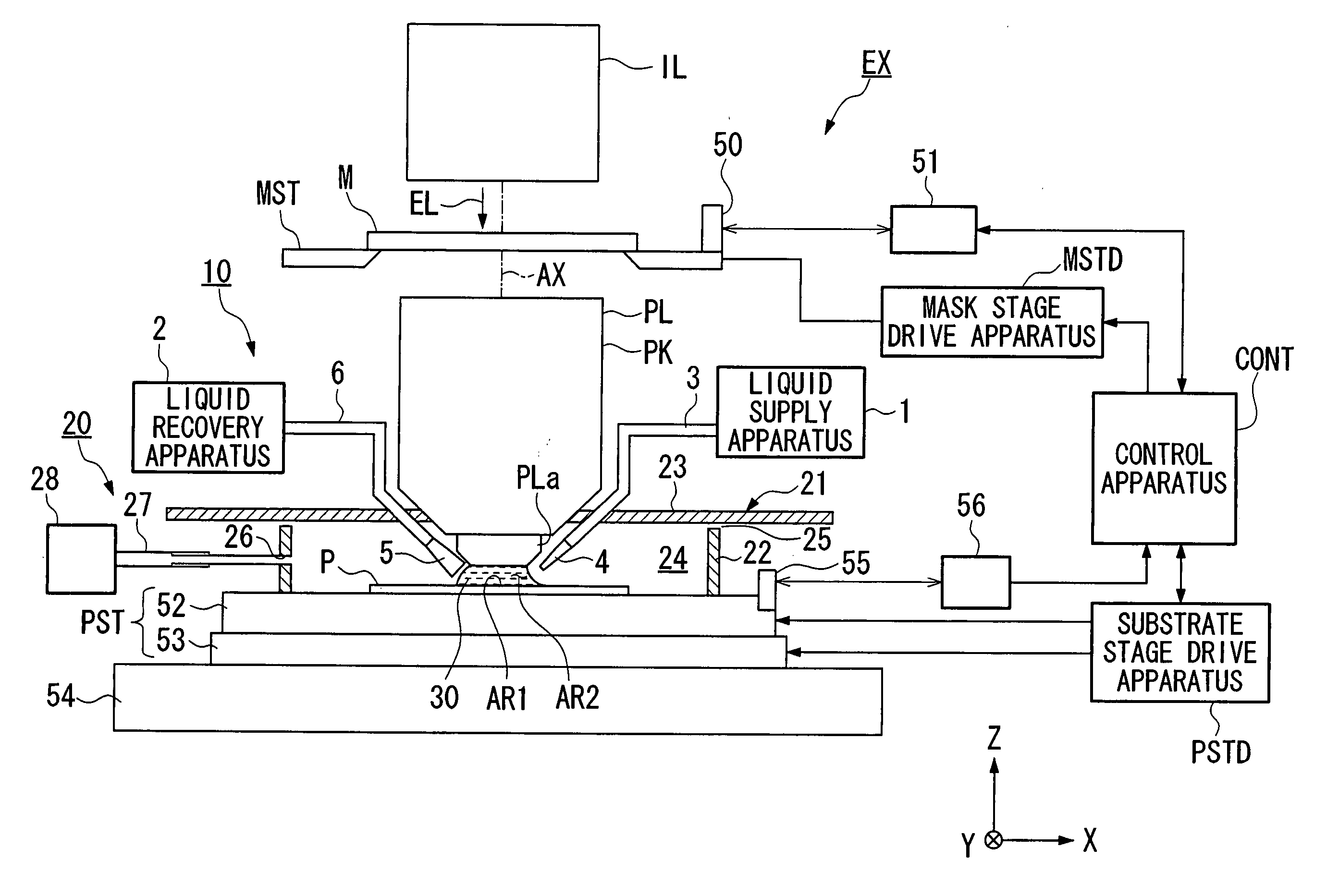
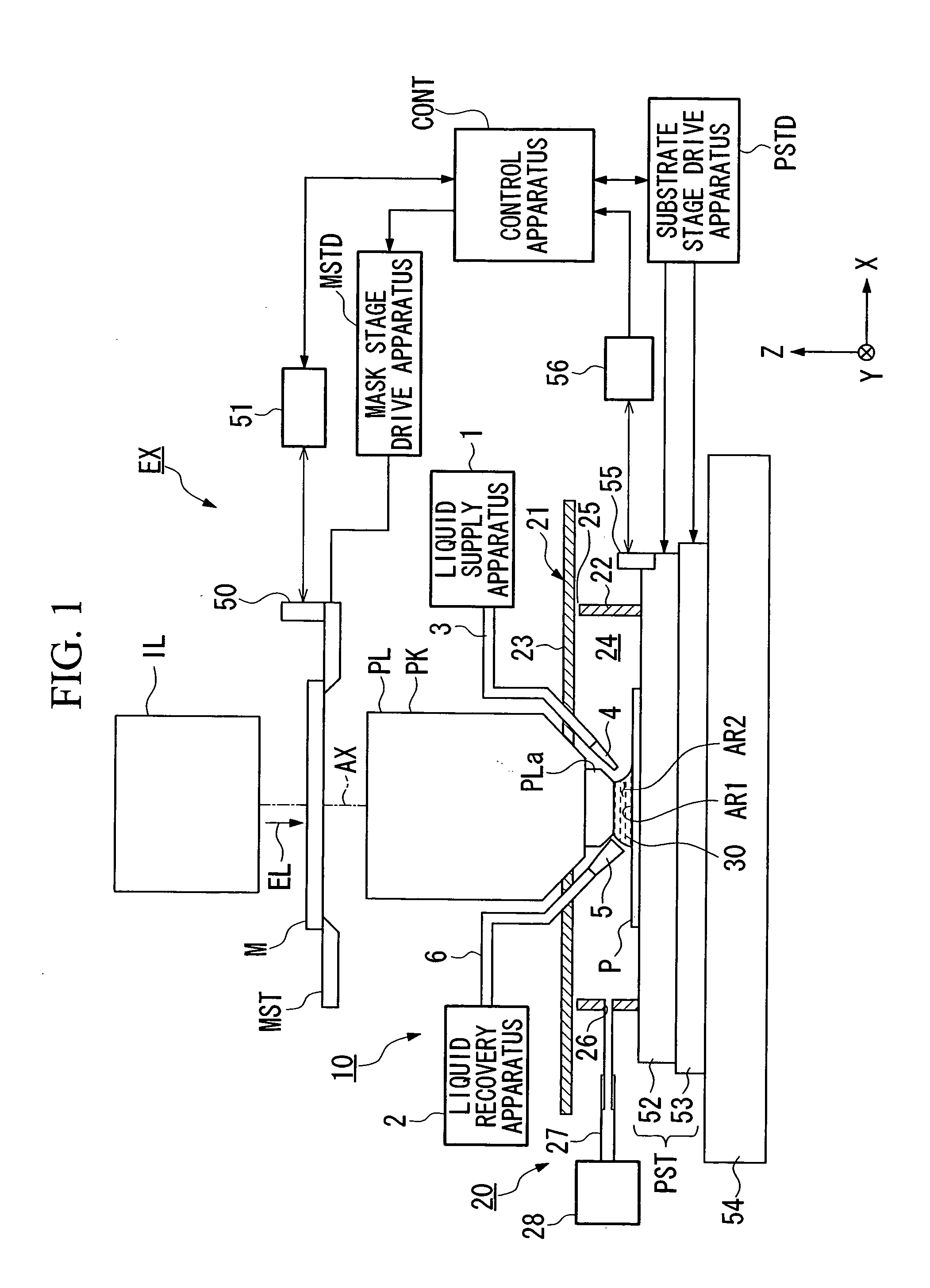
[0024]FIG. 1 is a schematic diagram that depicts the first embodiment of an exposure apparatus EX according to the present invention.

[0025] In FIG. 1, the exposure apparatus EX includes a mask stage MST that supports a mask M, a substrate stage PST that supports a substrate P, an illumination optical system IL that illuminates with an exposure light EL the mask M supported by the mask stage MST, a projection optical system PL that projects and exposes a pattern image of the mask M illuminated by the exposure light EL onto the substrate P supported by the substrate stage PST, and a control apparatus CONT that provides overall control of t...


PUM


Abstract

This exposure system projects a pattern image onto a substrate via a projection optical system and a liquid to expose the substrate, with a space between the projection optical system and the substrate filled with the liquid. The exposure system is provided with a vaporization preventing unit for preventing the vaporization of the liquid.

Description

CROSS-REFERENCE TO RELATED APPLICATION [0001] This is a Continuation application of International Application No. PCT / JP2004 / 003928, filed Mar. 23, 2004, which claims priority to Japanese Patent Application No. 2003-83329, filed Mar. 25, 2003. The content of the aforementioned application is incorporated herein by reference. BACKGROUND OF THE INVENTION [0002] 1. Field of the Invention [0003] The present invention relates to an exposure apparatus that exposes a pattern on a substrate via a projection optical system and a liquid in a state wherein the liquid is filled in at least one part of a space between the projection optical system and the substrate; and a device fabrication method that uses this exposure apparatus. [0004] 2. Description of Related Art [0005] Semiconductor devices and liquid crystal devices are fabricated by a so-called photolithography technique, wherein a pattern formed on a mask is transferred onto a photosensitive substrate. [0006] An exposure apparatus used ...

Claims


Application Information

Patent Timeline
IPC IPC(8): G03B27/42G03F7/20
CPCG03B27/42G03F7/70858G03F7/70341G03F7/2012G03F7/2041H01L21/0274
Inventor KAMEYAMA, MASAOMI
Owner NIKON CORP
Learn More