Load Management for Displaying an Alarm Signal Indicator

a technology of load management and alarm signal, which is applied in the direction of program control, instruments, testing/monitoring control systems, etc., can solve the problems of reducing the performance of the control and monitoring of the (process-engineering) technical facility, and the alarm signal in accordance with the prior art can reach its limit,

Pending Publication Date: 2022-07-21
SIEMENS AG
View PDF6 Cites 0 Cited by
  • Summary
  • Abstract
  • Description
  • Claims
  • Application Information

AI Technical Summary

Benefits of technology

[0019]If the time budget would be overshot, then the operator station client is configured to limit the visual display of the alarm signal indicator. As a result, the operator station client can dynamically react to changing demands. A (temporary) failure of the display for control and monitoring can thus be effectively prevented, such that the technical facility can be controlled and monitored at any instant. These advantages primarily take effect with a long-lasting volatility of alarm changes, with a generally high emergence of alarms or with a sudden “plethora of alarms”. In addition, the inventive management system is advantageously suitable to an increased extent for implementation on different hardware platforms, as are particularly employed when web-based management systems are used.

Problems solved by technology

Event sequence indicators with alarm signals in accordance with the prior art can reach their limits in the case of long-lasting volatility of alarm changes, high alarm emergence or sudden alarm emergence and often can no longer adhere to the time contingents available to them for visualization.
This can lead to considerable losses in performance in the control and monitoring of the (process-engineering) technical facility through to failure of the control and monitoring.

Method used


Image

  • Load Management for Displaying an Alarm Signal Indicator
  • Load Management for Displaying an Alarm Signal Indicator

Examples


Embodiment Construction

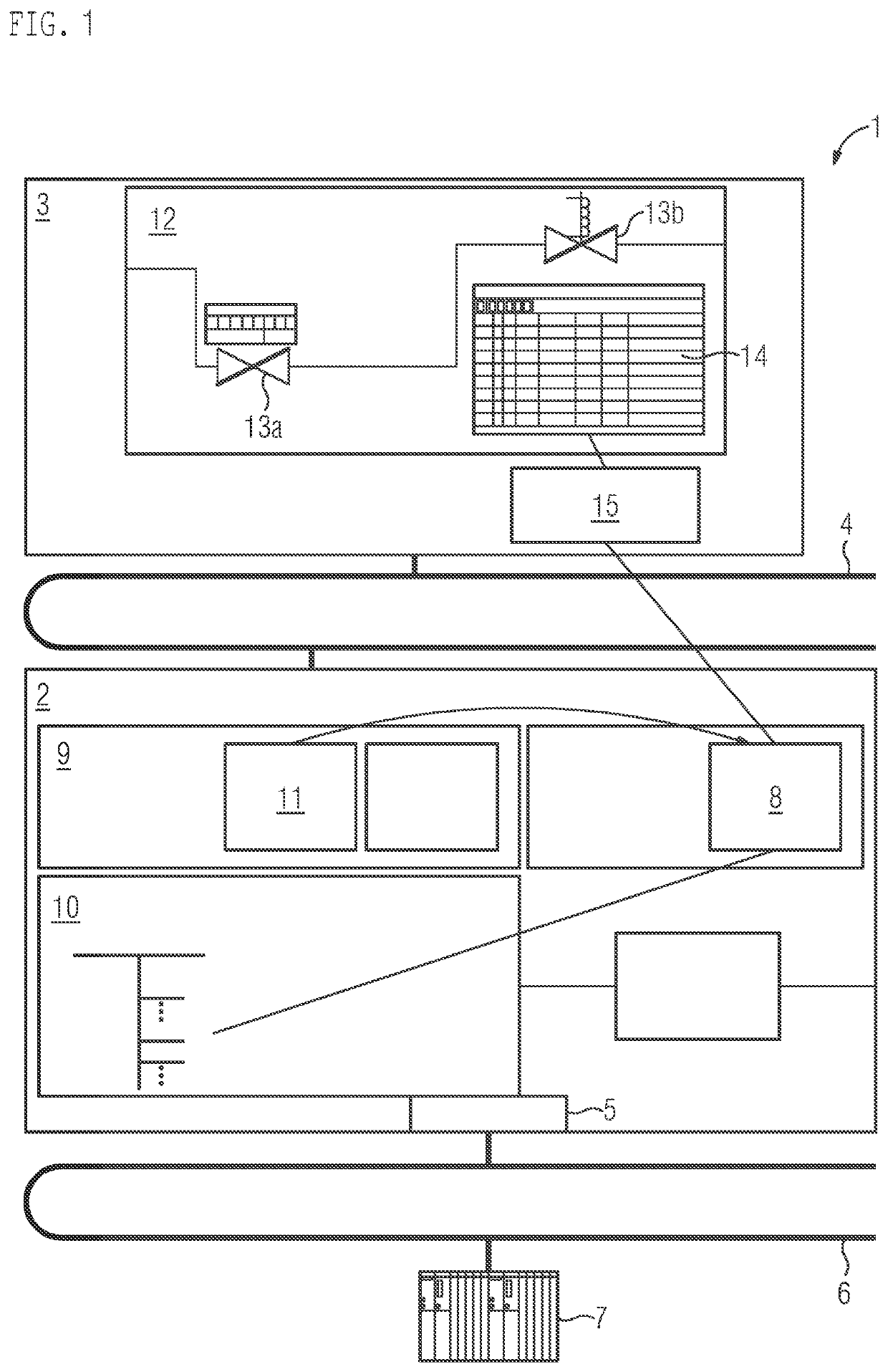
[0033]FIG. 1 shows part of an inventive management system 1 of a technical facility configured as a process facility, i.e., as a process-engineering facility. The management system 1 comprises an operator station server 2 and an operator station client 3.

[0034]The operator station server 2 and the operator station client 3 are interconnected via a terminal bus 4 and optionally to further components (not shown) of the management system 1 such as a process data archive.

[0035]A user or an operator can access the operator station server 2 for the purpose of control and monitoring via the operator station client 3 via the terminal bus 4. The terminal bus 4 can be configured, for example, as an industrial Ethernet, without being limited thereto.

[0036]The operator station server 2 has a device interface 5, which is connected to a facility bus 6. The operator station server 2 can communicate via this device interface 5 with an automation device 7 and with optionally available further compon...


PUM


Abstract

A method for visually displaying a facility mimic diagram of a technical facility which has an operator station server and an operator station client, wherein the method includes transferring the facility mimic diagram from the operator station server to the operator station client, where the facility mimic diagram includes an alarm signal indicator, communicating a duration for visually displaying the indicator, visually displaying the facility mimic diagram with the alarm signal indicator, informing the operator station client about an emergence of a new alarm signal in the management system via a message, determining a value an actual display time has to visually display the alarm signal indicator, determining whether a display time for the visual display of the alarm signal indicator with the new alarm signal would overshoot the value of the duration, limiting the visual display of the alarm signal indicator when the available duration is overshot.

Description

BACKGROUND OF THE INVENTION1. Field of the Invention[0001]The invention relates to use of a management system, a method for visual display of a facility mimic diagram of a technical facility the management system for the technical facility, in particular a process or manufacturing facility, which has an operator station server and an operator station client, where for control and monitoring the operator station server is configured to transfer a facility mimic diagram of the technical facility to the operator station client, where the facility mimic diagram comprises an alarm signal indicator, and where the operator station client is configured to visually display the facility mimic diagram with the alarm signal indicator.2. Description of the Related Art[0002]For the control and monitoring of process-engineering facilities, management systems of the process-engineering facilities create symbolic facility mimic diagrams, where these diagrams display the process-engineering connectio...

Claims


Application Information

Patent Timeline
Patent Type & Authority Applications(United States)
IPC IPC(8): G05B23/02
CPCG05B23/027G05B23/0272G05B23/0262G05B23/0216G05B19/0428G05B2219/24024G05B2219/31472G05B23/0267
Inventor LUTZ, BENJAMINKLUGE, GEORG
Owner SIEMENS AG
Why Eureka
Try Eureka