
Wind turbine tower with crane connection elements and a crane with tower flange connection elements

a technology of cranes and connection elements, which is applied in the direction of sustainable buildings, machines/engines, transportation and packaging, etc., can solve problems such as damage to the tower section

Pending Publication Date: 2022-07-28
ELEVATORRA IP APS
View PDF0 Cites 1 Cited by
  • Summary
  • Abstract
  • Description
  • Claims
  • Application Information

AI Technical Summary

Benefits of technology

The patent text describes a wind turbine tower and crane connection system that allows for easy attachment of a crane to the wind turbine tower. The crane connection elements are designed to safely support heavy loads, without causing damage or deformation to the tower. The crane can also include a moment compensating mechanism to reduce the moment loads on the tower section. Additionally, the crane can be positioned at various angles to adjust the moment compensation. The technical effects of this patent are improved safety and load capacity of the wind turbine tower and crane connection system.

Problems solved by technology

This is in contrast to prior art solutions where the crane needs to be strapped or connected to the outer surface of the tower sections which can result in damage to the tower section.

Method used


Image

  • Wind turbine tower with crane connection elements and a crane with tower flange connection elements
  • Wind turbine tower with crane connection elements and a crane with tower flange connection elements
  • Wind turbine tower with crane connection elements and a crane with tower flange connection elements

Examples


Embodiment Construction

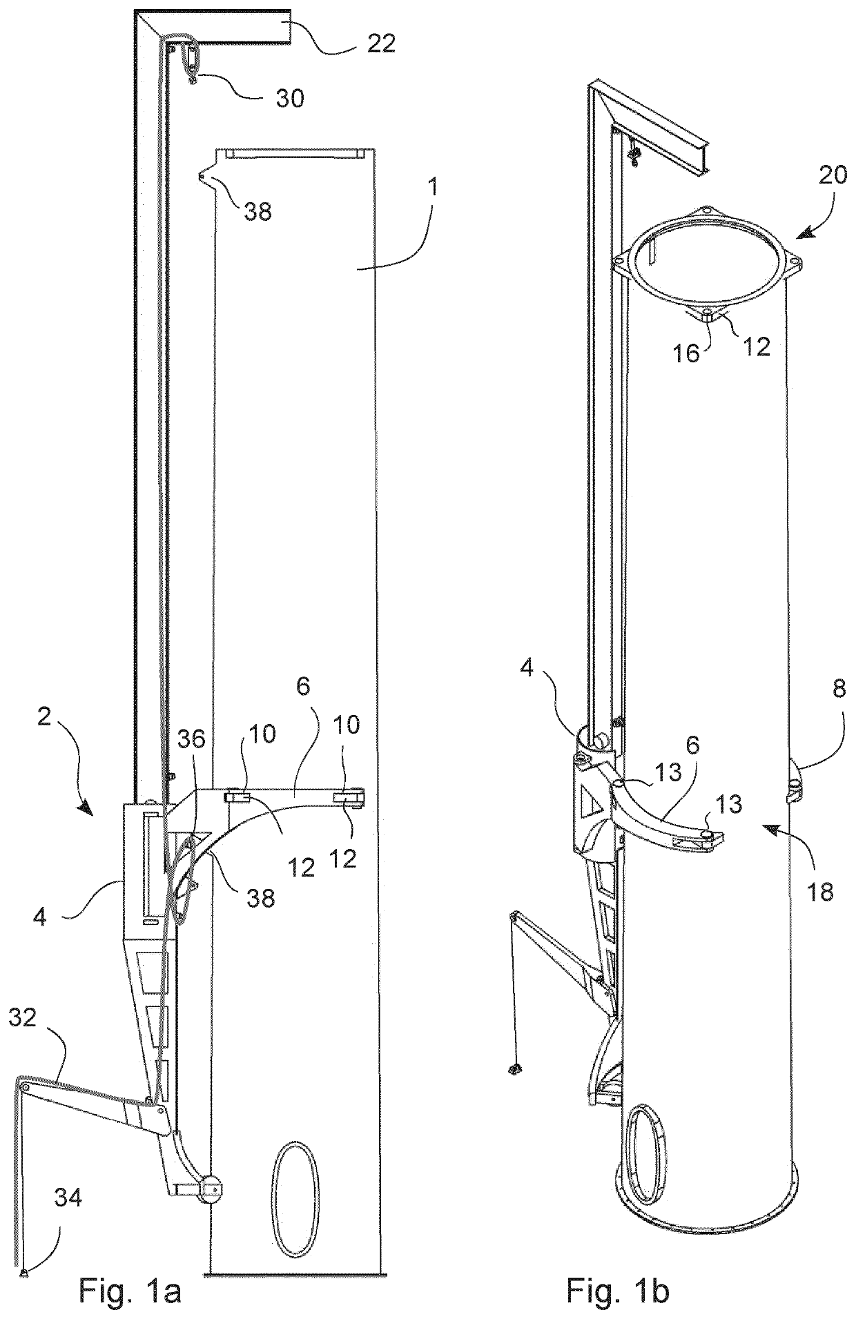
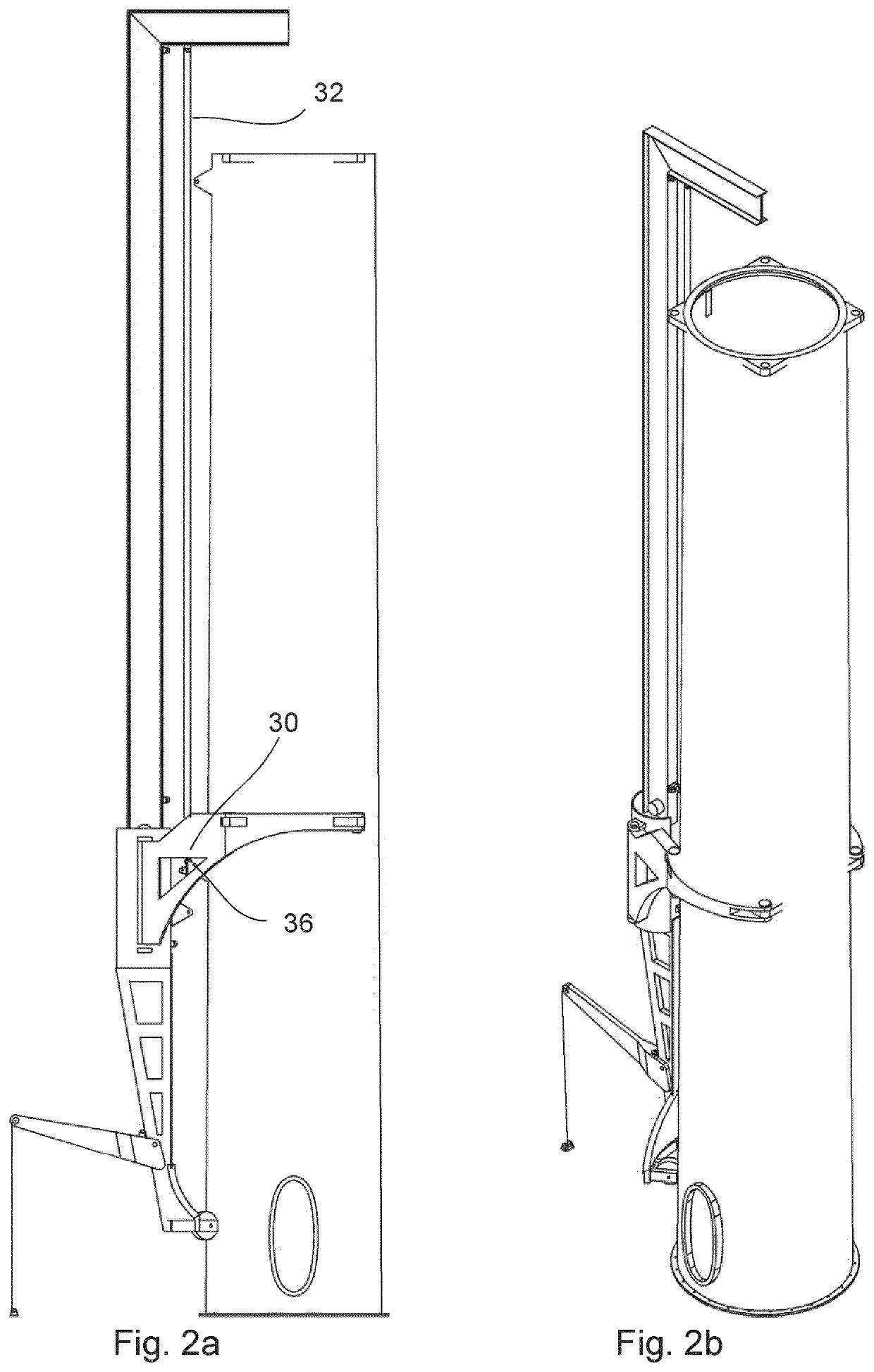
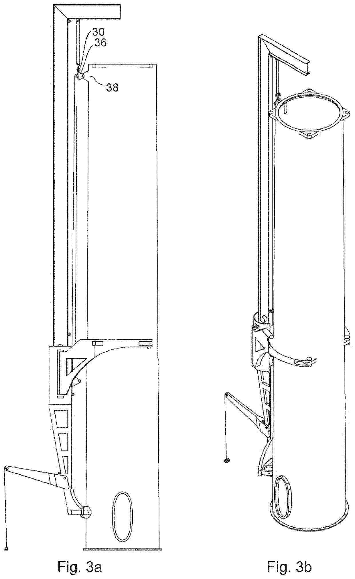
[0065]FIGS. 1a to 11b show eleven steps of a method for assembling a wind turbine tower, placing the nacelle on the top of the tower and mounting the blades to the nacelle. The method used in the figures makes use of a novel type of crane and a tower section with a novel flange to enable the assembly method.

[0066]The function of the crane and the flange will be described with reference to the method steps to better illustrate the function.

[0067]In FIG. 1a+1b, a base tower section 1 has been erected on a supporting surface (not shown), in a manner which is known in the art. The base tower section is typically bolted to a foundation element (not shown) as is known in the art.

[0068]Once the base tower section is erected, a crane 2 is connected to the base tower section 1. The crane comprises a base portion 4, and two arms 6, 8 pivotably connected to the base portion. The two arms are arranged to pivot around a vertical axis so that they can be pivoted into connection with the tower sec...


PUM


Abstract

A crane (2) comprising a base portion (4), two arms (6, 8) displaceably connected to the base portion and a lifting boom (22) displaceably connected to the base portion, said lifting boom being provided with a lifting wire (32) and a lifting member (30), for example a lifting hook, for lifting a load, wherein the two arms and the base portion in combination comprise at least three tower flange connection element (10) is arranged to be detachably connectable to cooperating crane connection elements on a flange of a wind turbine tower section, wherein each arm comprises one of the tower flange connection elements, and wherein the vertical distance between any two tower flange connection elements in the normal operating position of the crane is less than 1 m, less than 50 cm or less than 25 cm. In this way a crane is provided which can be attached to a flange located at the upper portion of a tower section.

Description

[0001]The current invention relates to a wind turbine tower with crane connection elements and a crane for being connected to crane connection elements on a wind turbine tower. The current invention also relates to a method of assembling a wind turbine tower with the crane.[0002]It should be noted that the term “wind turbine tower” should be understood as a tower for a wind turbine. This could either refer to the final completed tower or to a tower which is in the process of being assembled. For example, a single tower section anchored on the ground, is considered a wind turbine tower under construction according to the current specification. The term “wind turbine tower” as used in the claims should cover this partially assembled wind turbine tower.[0003]The current specification also discloses independent inventions directed to a novel self-hoisting crane and to a crane with a novel moment compensating mechanism.DESCRIPTION OF RELATED ART[0004]Typically when doing maintenance and / ...

Claims


Application Information

Patent Timeline
IPC IPC(8): F03D13/10F03D13/20B66C23/20B66C1/10
CPCF03D13/10F03D13/20B66C23/207F05B2230/61F05B2240/912F05B2230/604B66C1/108B66C23/32Y02B10/30Y02E10/72
Inventor FENGER, PER ESKE
Owner ELEVATORRA IP APS
Learn More