Fixing device and image forming apparatus

a technology of fixing device and image forming apparatus, which is applied in the direction of electrographic process apparatus, instruments, optics, etc., can solve the problems of inability to transfer and degrade image quality, and achieve the effect of preventing the temperature drop reducing the thermal diffusivity of the heat storage member, and ensuring the transfer of hea

Pending Publication Date: 2022-07-28
OKI ELECTRIC IND CO LTD
View PDF8 Cites 1 Cited by
  • Summary
  • Abstract
  • Description
  • Claims
  • Application Information

AI Technical Summary

Benefits of technology

[0006]An object of the present disclosure is to provide a fixing device and an image forming apparatus capable of stabilizing heat transfer to an annular belt and improving an image quality.
[0008]Since the heat storage member is disposed on the side of the heating member opposite to the fixing belt, and the thermal diffusivity of the heat storage member is lower than that of the annular belt, sufficient heat can be stored in the heat storage member, and a decrease in the temperature of the heat storage member can be prevented.
[0009]Therefore, heat can be sufficiently transferred to the annular belt. Further, heat taken away from the annular belt when the sheet passes a fixing nip can be replenished by the heat storage member via the heating member. Thus, the temperature of the annular belt can be made uniform and a gloss difference in an image can be reduced. As a result, the image quality can be improved.

Problems solved by technology

However, in the conventional fixing device, heat cannot be transferred stably to the fixing belt when printing is performed at high speed, and an image quality may be degraded.

Method used


Image

  • Fixing device and image forming apparatus
  • Fixing device and image forming apparatus
  • Fixing device and image forming apparatus

Examples


Embodiment Construction

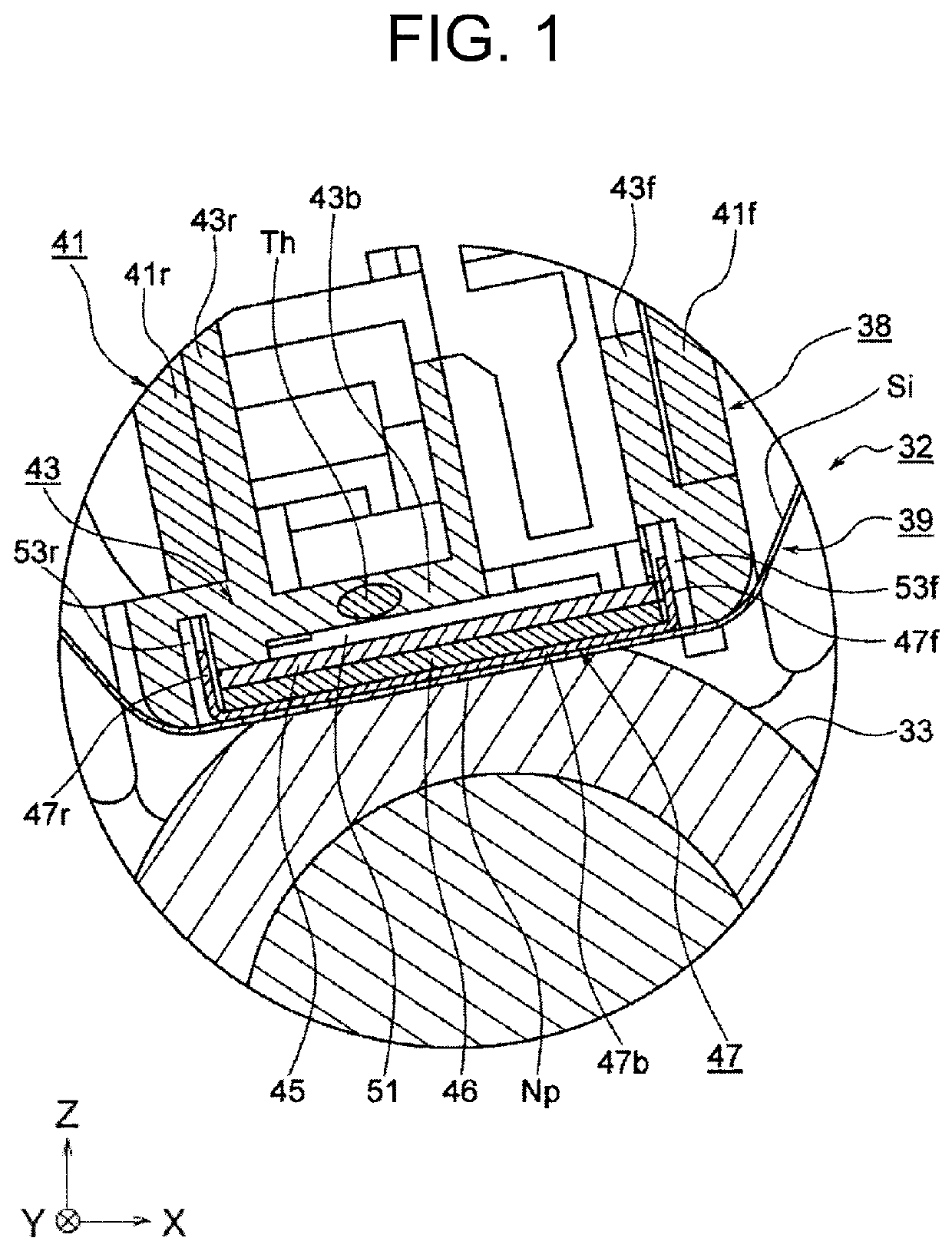
[0029]Embodiments of the present disclosure will be described in detail below with reference to the drawings. Herein, a fixing device and a printer as an image forming apparatus will be described.

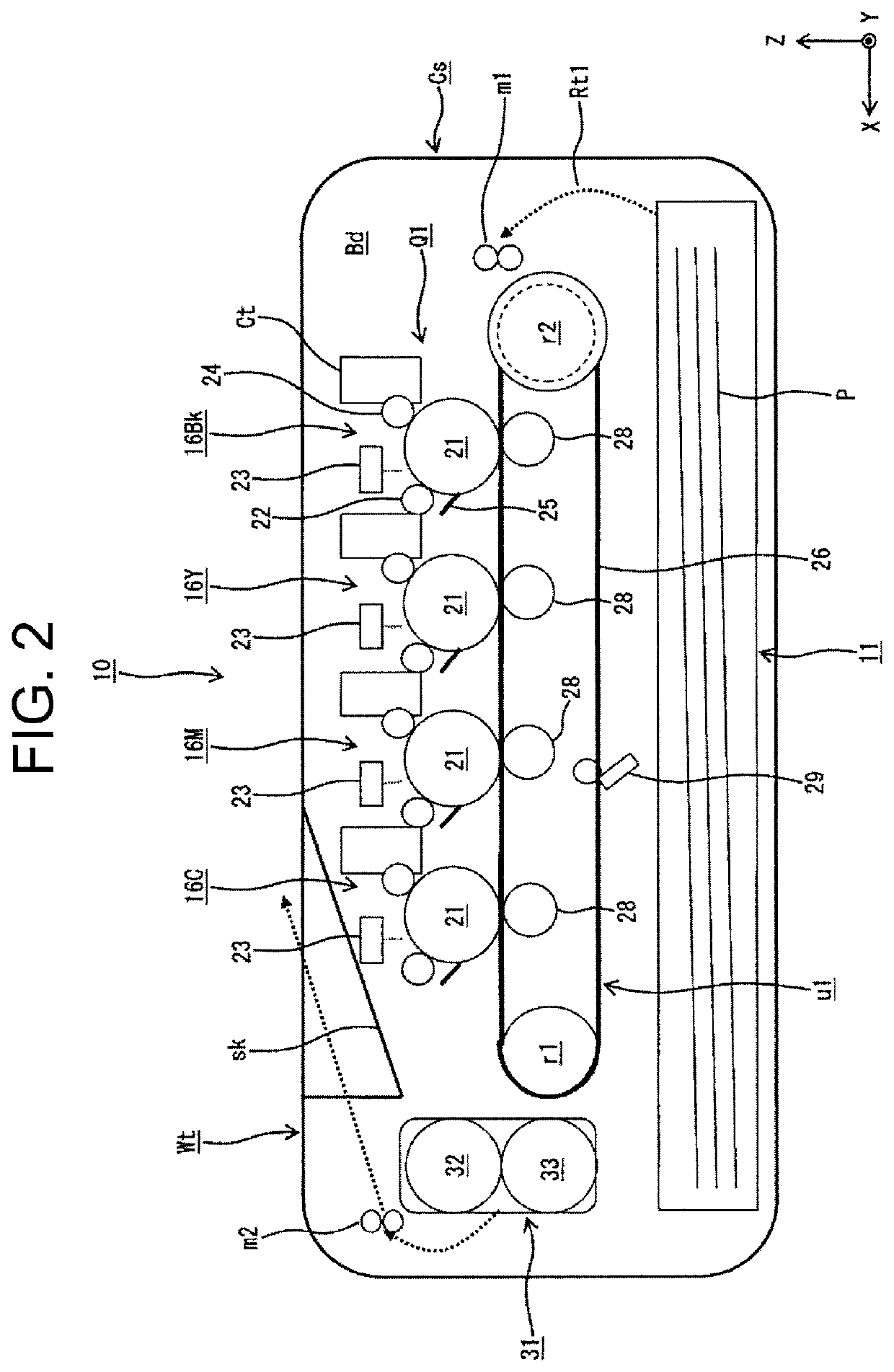
[0030]FIG. 2 is a schematic diagram of a printer 10 in the embodiment. In FIG. 2, a +X axis direction is a rearward direction of the printer 10, while a −X axis direction is a frontward direction of the printer 10. A +Y axis direction is a left direction of the printer 10, while a −Y axis direction is a right direction of the printer 10. A +Z-axis direction is an upward direction of the printer 10, while a −Z axis direction is a downward direction of the printer 10.

[0031]In FIG. 2, reference numeral 10 denotes the printer, reference numeral Cs denotes a housing of the printer 10, and reference numeral Bd denotes a main body of the printer 10. The housing Cs serves as an enclosure of the printer 10. The main body Bd is also referred to as an apparatus main body.

[0032]A sheet cassette 11 as a...


PUM


Abstract

A fixing device includes an annular belt, a heating member disposed to face an inner circumferential surface of the annular belt; and a heat storage member disposed to face a surface of the heating member on a side opposite to the annular belt. A thermal diffusivity of the heat storage member is lower than a thermal diffusivity of the annular belt.

Description

BACKGROUND OF THE INVENTION1. Field of the Invention[0001]The present disclosure relates to a fixing device and an image forming apparatus.2. Description of the Related Art[0002]There are image forming apparatuses such as a printer, a copier, and a facsimile machine. The image forming apparatus (for example, the printer) includes an image bearing body. A surface of the image bearing body is uniformly charged by a charging member. The surface of the image bearing body is exposed with light emitted by an exposure device so that an electrostatic latent image is formed thereon. The electrostatic latent image is developed by a developer bearing body to form a toner image. Then, a sheet transported from a sheet cassette is introduced between the image bearing body and a transfer member, and the toner image is transferred to the sheet by the transfer member. Then, the sheet is transported to a fixing device or a fuser. The fixing device fixes the toner image to the sheet, so that printing ...

Claims


Application Information

Patent Timeline
Patent Type & Authority Applications(United States)
IPC IPC(8): G03G15/20
CPCG03G15/2053G03G15/2039G03G15/2064G03G15/2042G03G2215/2035G03G15/2057
Inventor UBAGAI, AKIRA
Owner OKI ELECTRIC IND CO LTD
Why Eureka
Try Eureka