Massage armchair, and massage mechanism and massage method thereof

a technology of massage armchair and massage mechanism, which is applied in the field of massage chairs, can solve the problems that the motion conversion device itself does not have a sufficient supporting strength to sustain the satisfactory strength for a long time, and the shoulder-clamping massage mechanism cannot achieve the satisfactory strength of human body massage, so as to reduce the size of the entire mechanism, simple structure, and simple

Pending Publication Date: 2022-08-04
HENGLIN HOME FURNISHINGS CO LTD
View PDF0 Cites 1 Cited by
  • Summary
  • Abstract
  • Description
  • Claims
  • Application Information

AI Technical Summary

Benefits of technology

This patent describes a massage mechanism that can complete both shoulder-clamping and kneading actions with only one shaft. The mechanism uses a percussion shaft to achieve the percussion action. The design also synchronizes the horizontal movements of the connecting member and the supporting seat assembly, while making their vertical movements different. This synchronization allows for a more effective massage. The structure is simple, reducing the size of the entire mechanism.

Problems solved by technology

However, those skilled in the art found that, during the use process, in the motion conversion devices mentioned above, due to the limitation of the parts themselves and the connection relationship between them, the shoulder-clamping massage mechanism cannot achieve a satisfactory strength during the massage process for human body.
Even when the shoulder-clamping massage mechanism can achieve a satisfactory strength, the motion conversion device itself does not have a sufficient supporting strength to sustain the satisfactory strength for a long time.

Method used


Image

  • Massage armchair, and massage mechanism and massage method thereof
  • Massage armchair, and massage mechanism and massage method thereof
  • Massage armchair, and massage mechanism and massage method thereof

Examples


first embodiment

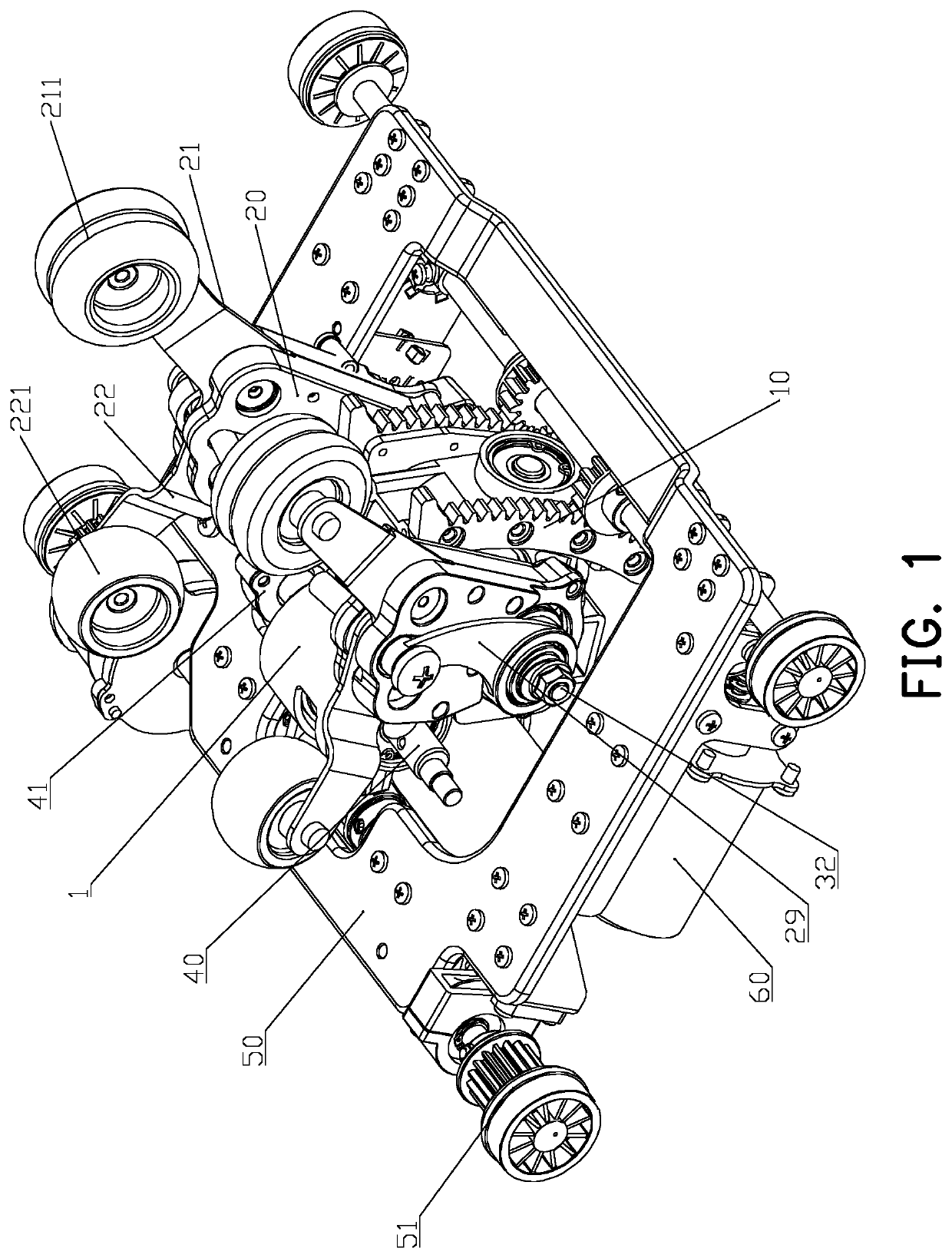
[0062]A shoulder-clamping massage mechanism as shown in FIG. 6 and FIG. 7 includes a supporting seat assembly 20, an upper massage arm 21 and a lower massage arm 22 mounted on a supporting seat assembly 20, and an upper massage rolling wheel 211 mounted on top of the upper massage arm 21 and a lower massage rolling wheel 221 mounted at the top of the lower massage arm 22 in the manner of rolling circumferentially. The improvement being made is that a connecting shaft 23 and a first driving assembly 31 are further provided. The connecting shaft 23 is movable on the supporting seat assembly 20. The bottom end of the upper massage arm 21 is rotatably connected to the connecting shaft 23, and the bottom end of the lower massage arm 22 is rotatably connected to the connecting shaft 23. The first driving assembly 31 is configured to drive the connecting shaft 23 to reciprocate up and down on the supporting seat assembly 20, so that the upper massage arm 21 rotates relative to the supporti...

second embodiment

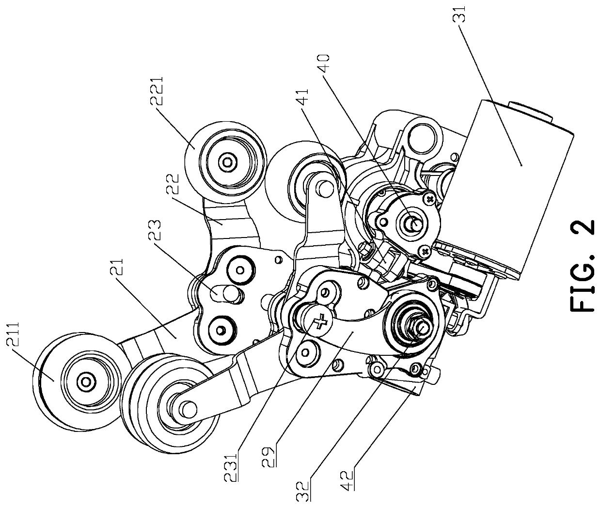
[0092]In this embodiment, the shoulder-clamping massage mechanism cooperates with the kneading shaft 32 to form a clamping-kneading massage mechanism as shown in FIG. 3. In this manner, other than the existing massage motion, the shoulder-clamping massage mechanism can further integrate the kneading massage technique to realize the combination of different massage techniques.

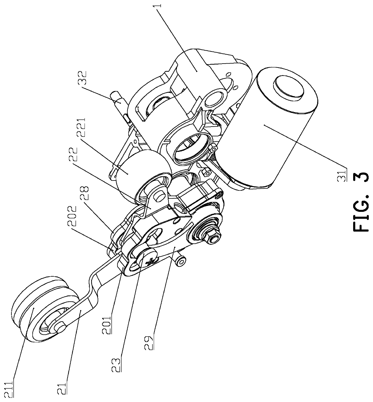
[0093]A clamping and kneading massage mechanism is as shown in FIG. 3, FIG. 15 and FIG. 16, including two shoulder-clamping massage mechanisms as described in the first embodiment, and also including a connecting seat 1, a first driving assembly 31, a first connecting member 29, and a kneading shaft 32. The two shoulder-clamping massage mechanisms are arranged on both sides of the connecting seat 1 through the kneading shaft 32. The kneading shaft 32 is arranged on the connecting seat 1 and is connected to the two supporting seat assemblies 20 on the left and right sides of the connecting seat 1. The kneading sh...

third embodiment

[0128]In this embodiment, the shoulder-clamping and kneading massage mechanism described in the second embodiment cooperates with the percussion shaft 40 to form a clamping-kneading-percussion massage mechanism as shown in FIG. 3. In this manner, other than the existing massage motion, the shoulder-clamping and kneading massage mechanism can further integrate the percussion massage technique to realize the combination of different massage techniques.

[0129]A clamping and kneading massage mechanism as shown in FIG. 2 includes the clamping and kneading massage mechanism as described in the second embodiment, and further includes a percussion shaft 40 arranged on the connecting seat 1, a percussion assembly 41, and a second driving assembly 42. The percussion shaft 40 is distributed parallel to the kneading shaft 32, and is spaced from the kneading shaft 32 at a certain distance, so that at least the shaft end of the kneading shaft 32 does not pass through the area where the supporting ...


PUM


Abstract

A massage mechanism includes a connecting seat, a supporting seat assembly, upper massage arms, lower massage arms, a kneading shaft and a first driving assembly. The first driving assembly is used for driving the kneading shaft to rotate, such that a connecting member and a connecting shaft are driven to perform a reciprocating motion on each supporting seat assembly, and upper massage rolling wheels and lower massage rolling wheels are close to each other or away from each other, so as to achieve a shoulder clamping action. The two upper massage arms and the upper massage rolling wheels are driven to be close to each other or away from each other, and the two lower massage arms and the lower massage rolling wheels are close to each other or away from each other, so as to achieve a kneading action.

Description

FIELD OF THE DISCLOSURE[0001]The disclosure relates to the field of massage chairs, in particular to a massage armchair, and a massage mechanism and a massage method thereof.DESCRIPTION OF RELATED ART[0002]A massage mechanism with a shoulder-clamping massage function is one of the key design of the massage mechanism, which can bring varieties to the massage techniques that the massage mechanism can achieve.[0003]The patent application with the publication number CN100382775C discloses a massage mechanism scheme with shoulder-clamping massage function. A first massage finger and a second massage finger of the scheme can move close to or away from each other to massage the user's shoulders when a kneading shaft (also known as a kneading driving shaft) rotates. The patent application with publication number TW201410230A discloses another massage mechanism scheme with a shoulder-clamping massage function. This scheme also allows the upper and lower therapeutic devices to move close to o...

Claims


Application Information

Patent Timeline
Patent Type & Authority Applications(United States)
IPC IPC(8): A61H7/00A61H15/00
CPCA61H7/007A61H7/004A61H15/00A61H2201/0134A61H2201/0149A61H2015/0007A61H2201/1623A61H2201/1635A61H2201/1671A61H2201/1669A61H2201/1614A61H2205/062A61H2201/1215A61H2007/009A61H15/0078A61H23/006A61H2015/0028A61H23/02A61H7/00A61H2201/1633
Inventor WANG, JIANGLIN
Owner HENGLIN HOME FURNISHINGS CO LTD
Why Eureka
Try Eureka