
Recursive coupling of artificial learning units

a technology of artificial learning and coupling, applied in the field of recursive coupling of artificial learning units, can solve the problems of inability to fully retrain, system essentially useless in other domains, and inability to achieve real-time responses, and methods still show great differences in human intelligen

Pending Publication Date: 2022-08-04
FRAUNHOFER GESELLSCHAFT ZUR FOERDERUNG DER ANGEWANDTEN FORSCHUNG EV +1
View PDF0 Cites 0 Cited by
  • Summary
  • Abstract
  • Description
  • Claims
  • Application Information

AI Technical Summary

Benefits of technology

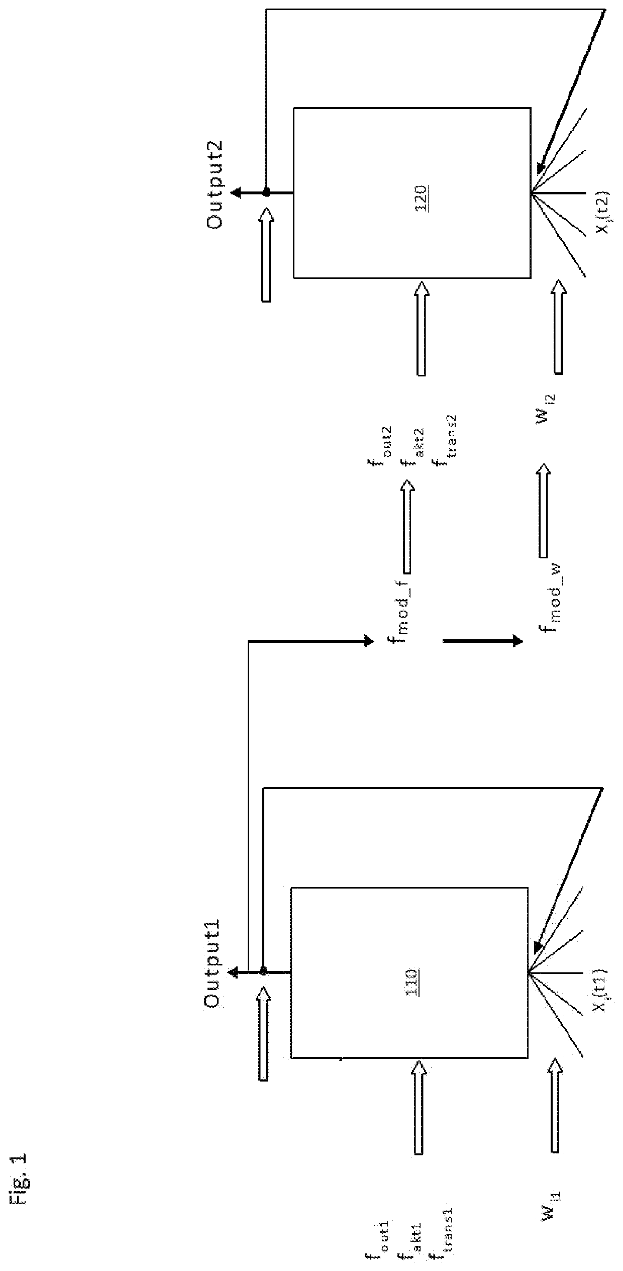
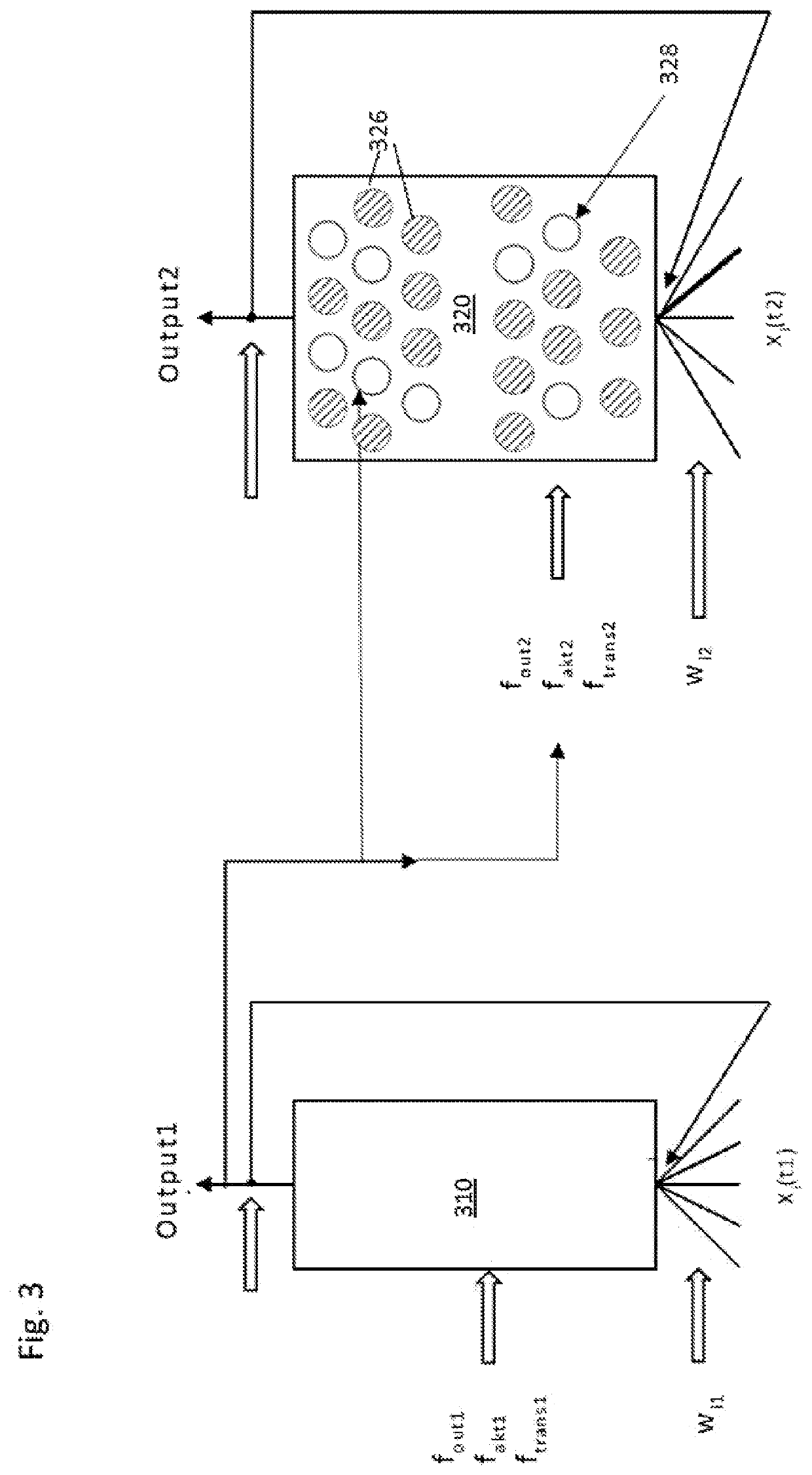
This patent describes a method for coupling artificial intelligence units together without using direct feedback of input or output values. The first artificial intelligence unit obtains input values and forms modulation functions based on these values. These functions are then applied to parameters of the second artificial intelligence unit to affect its processing. The second unit obtains output values, which may be modulated versions of the initial inputs. This coupling leads to different results or output values compared to conventional learning units, resulting in a more efficient and faster problem solution. The first and second units can perform parallel or time-dependent evaluations of the input values. The second unit may also use a neural network with deactivated nodes based on the output values of the first unit. The method allows for the meaningful coupling and synchronization of multiple artificial intelligence units. The designated dominant unit can be determined based on its output values and the solution developed by the system can be stopped or aborted within a predetermined time period.

Problems solved by technology

At the same time, these systems are essentially useless in other domains and must be completely retrained for other applications or even trained using completely different approaches.
Real-time responses thus quickly become impossible.
It is obvious that these methods still show great differences to human intelligence.

Method used


Image

  • Recursive coupling of artificial learning units
  • Recursive coupling of artificial learning units
  • Recursive coupling of artificial learning units

Examples


example g

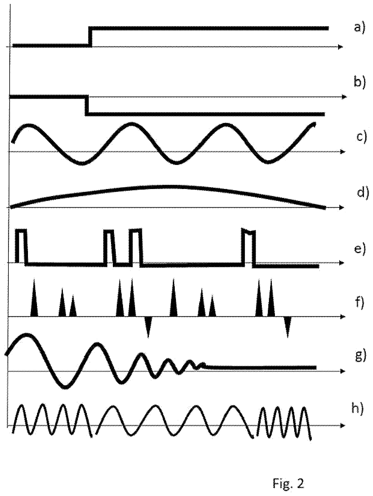
[0053) in FIG. 2 further shows a damped oscillation, which could also be arbitrarily designed with different dampings and amplitudes. Finally, example h) shows a time sequence of different oscillations around the fundamental value, where in particular the period lengths of the oscillations differ, while the amplitude remains the same. This combination of different oscillations can also be designed as an additive superposition, i.e. beat.

[0054]In general, any modulation functions are conceivable and the functions shown in FIG. 2 are only to be understood as examples. In particular, any combination of the example functions shown is possible. It is also understood that the baseline shown in all examples can run at 0 or at another basic value, depending on the desired effect of the modulation function. For a pure concatenation of the modulation function with the respective modulated function, a base value of 0 and corresponding increases in the function value can be used to ensure that ...


PUM


Abstract

Provided is a method in a system of at least two artificial intelligence units, comprising inputting input values to at least a first artificial intelligence unit and a second artificial intelligence unit; obtaining first output values of the first artificial intelligence unit; forming one or more modulation functions based on the output values of the first artificial intelligence unit; applying the formed one or more modulation functions to one or more parameters of the second artificial intelligence unit, the one or more parameters influencing the processing of input values and the obtaining of output values in the second artificial intelligence unit; and finally obtaining second output values of the second artificial intelligence unit.

Description

[0001]The present invention relates to a method for recursively coupling artificial intelligence units.PRIOR ART[0002]Artificial intelligence now plays an increasing role in countless areas of application. This is initially understood to mean any automation of intelligent behavior and machine learning. However, such systems are usually intended and trained for special tasks. This form of artificial intelligence (AI) is often referred to as “weak AI” and is essentially based on the application of computations and algorithms to simulate intelligent behavior in a fixed domain. Examples include systems that are able to recognize certain patterns, such as safety systems in vehicles, or that can learn and implement certain rules, such as in chess. At the same time, these systems are essentially useless in other domains and must be completely retrained for other applications or even trained using completely different approaches.[0003]For the practical implementation of such artificial inte...

Claims


Application Information

Patent Timeline
IPC IPC(8): G06N3/04G06N3/08
CPCG06N3/0454G06N3/084G06N3/082G06N3/045G06N3/049G06N3/08
Inventor ZIMMERMANN, HEIKOFUHR, GÜNTERFUHR, ANTONIE
Owner FRAUNHOFER GESELLSCHAFT ZUR FOERDERUNG DER ANGEWANDTEN FORSCHUNG EV
Learn More