
Functional safety techniques for industrial automation devices

Pending Publication Date: 2022-08-04
ROCKWELL AUTOMATION TECH
View PDF0 Cites 0 Cited by
  • Summary
  • Abstract
  • Description
  • Claims
  • Application Information

AI Technical Summary

Benefits of technology

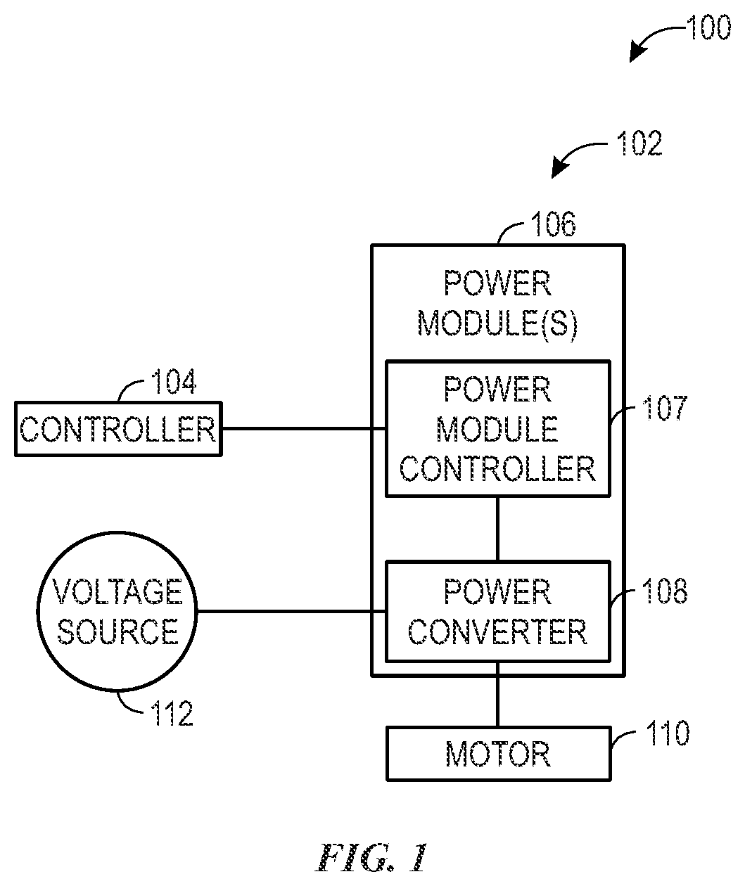
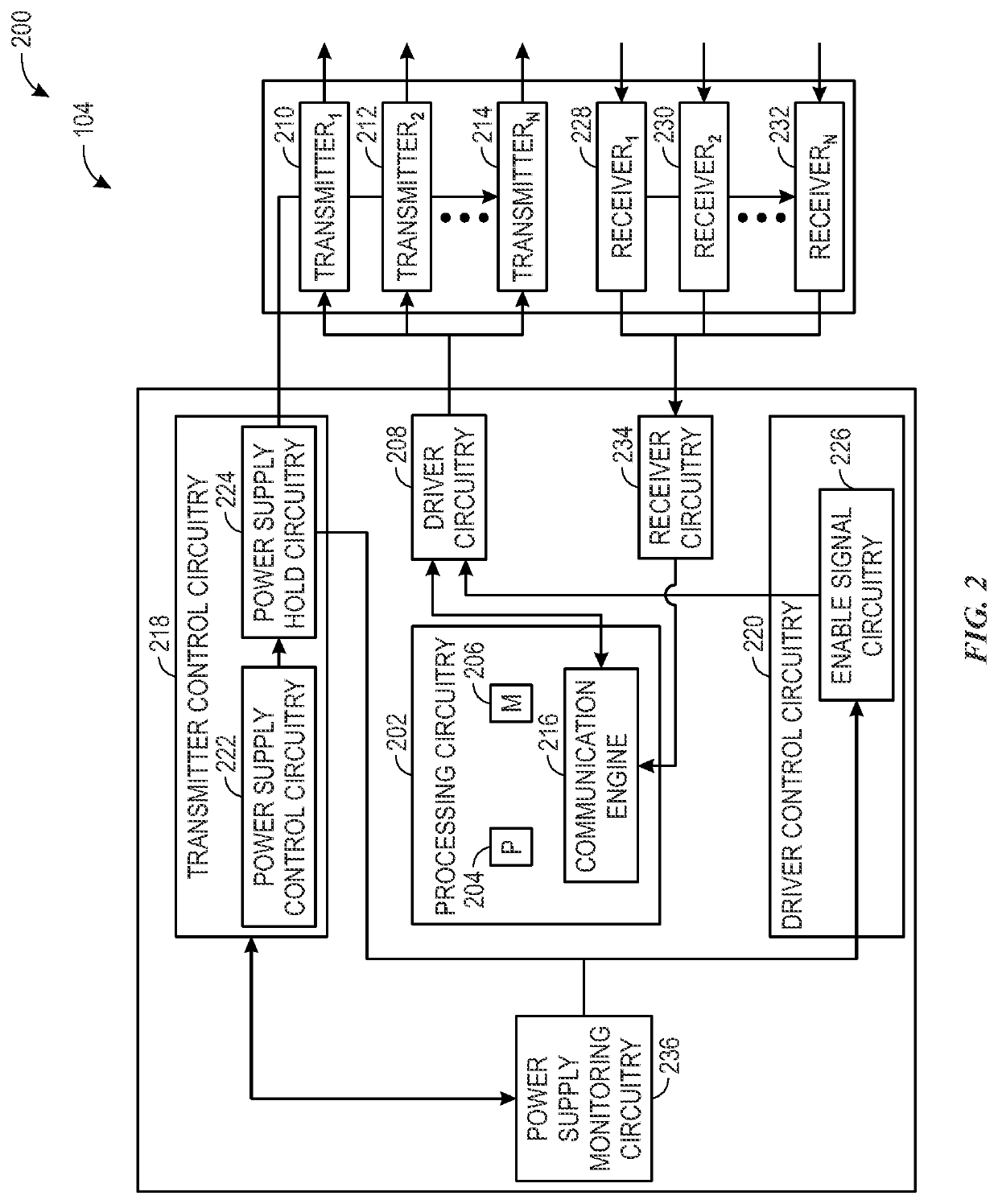
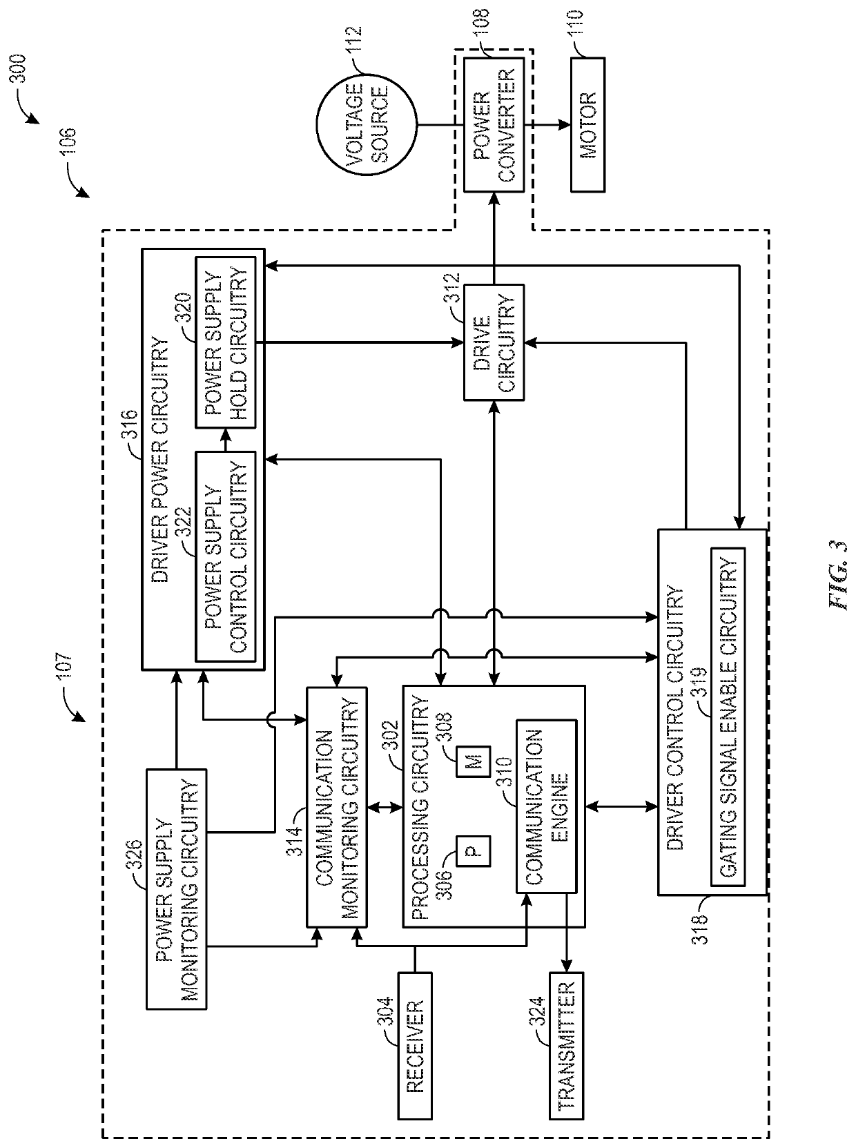
The patent text describes a system that includes a controller and two power modules. The controller sends a control signal to the power modules, and the power modules shut down when they receive a shutdown command. The system also includes a power converter that controls the operation of a motor. The power module detects if there is a lack of communication with the controller, and it sends a disable driver circuitry command and a prevent power from being provided to the driver circuitry command to the gating circuitry. The technical effect of this patent text is to provide a system that can quickly shut down power modules when they detect a lack of communication with the controller, thereby preventing power from being provided to the motor and improving operational efficiency.

Problems solved by technology

This may lead to complex and expensive circuit board designs.
Additionally, development of the safety messages may require extensive work in order to meet the functional safety standards.

Method used


Image

  • Functional safety techniques for industrial automation devices
  • Functional safety techniques for industrial automation devices
  • Functional safety techniques for industrial automation devices

Examples


Embodiment Construction

[0012]One or more specific embodiments of the present disclosure will be described below. In an effort to provide a concise description of these embodiments, all features of an actual implementation may not be described in the specification. It should be appreciated that in the development of any such actual implementation, as in any engineering or design project, numerous implementation-specific decisions must be made to achieve the developers' specific goals, such as compliance with system-related and business-related constraints, which may vary from one implementation to another. Moreover, it should be appreciated that such a development effort might be complex and time consuming, but would nevertheless be a routine undertaking of design, fabrication, and manufacture for those of ordinary skill having the benefit of this disclosure.

[0013]When introducing elements of various embodiments of the present disclosure, the articles “a,”“an,”“the,” and “said” are intended to mean that th...


PUM


Abstract

A method may include receiving, by respective processing circuitry of one or more power modules of an industrial automation device, a control signal from a controller of the industrial automation device. The power modules may include driver circuitry and a power converter that may provide power to a motor based on the signal. The method may also include, detecting, by the respective processing circuitry, a lack of communication from the controller based on the signal, and, in response to detecting the lack of communication from the controller, transmitting, by the respective processing circuitry, a first command to gating signal enable circuitry to disable the driver circuitry, and transmitting, by the respective processing circuitry, a second command to driver power circuitry to prevent power from being provided to the driver circuitry.

Description

BACKGROUND[0001]The disclosure generally relates to controlling, monitoring, and disabling an industrial automation device. More particularly, embodiments of the present disclosure are related to systems and methods for implementing a functional safety mechanism to prevent power from being provided to an industrial automation device and verifying that circuitry used to implement the functional safety mechanism is functioning properly.[0002]Industrial automation devices, such as medium voltage drives, are employed in a variety of environments. Under certain circumstances, these industrial automation devices are disabled and placed into a safe state. Accordingly, certain functional safety mechanisms may be designed to reliably disable the industrial automation devices under these circumstances. The design of such functional safety mechanisms may be designed to comply with certain functional safety standards, such as the International Electrotechnical Commission (IEC) 61508. One such f...

Claims


Application Information

Patent Timeline
IPC IPC(8): H02H7/20H02H1/00G05B19/05
CPCH02H7/20G05B2219/14116G05B19/058H02H1/0092H02P27/06H02M1/088G05B23/0291G05B19/048G05B2219/25158G05B2219/24125
Inventor CAMPBELL, AL J.ALLAN, JOHN DAVIDCHIS, MARIUS G.DRAKE, REGINALD A.BRAUN, SCOTT D.
Owner ROCKWELL AUTOMATION TECH
Learn More