Eureka AIR delivers breakthrough ideas for toughest innovation challenges, trusted by R&D personnel around the world.

Circuit board with sensor controlled lights and end-to-end connection

a technology of printed circuit boards and sensors, which is applied in the direction of light sources, lighting device details, lighting and heating apparatuses, etc., can solve the problems of large packaging size for implementing this functionality, and achieve the effects of reducing assembly complexity, reducing overall package size, and increasing system capacity

Active Publication Date: 2022-08-04
SNAP ON INC
View PDF8 Cites 0 Cited by
  • Summary
  • Abstract
  • Description
  • Claims
  • Application Information

AI Technical Summary

Benefits of technology

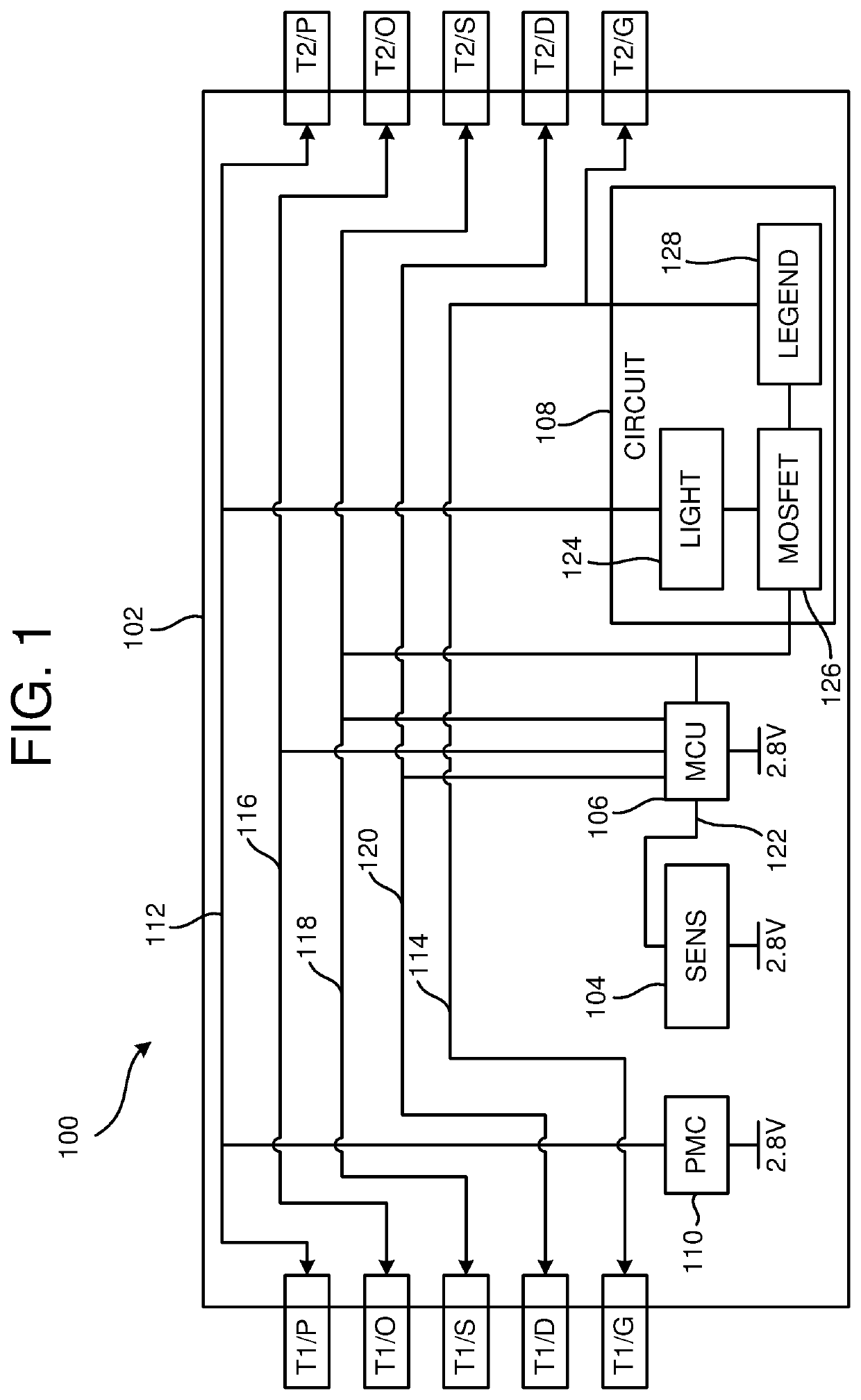
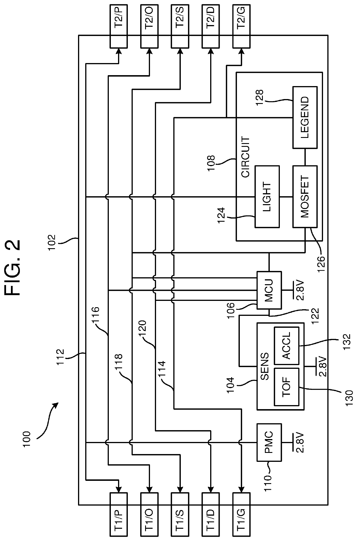
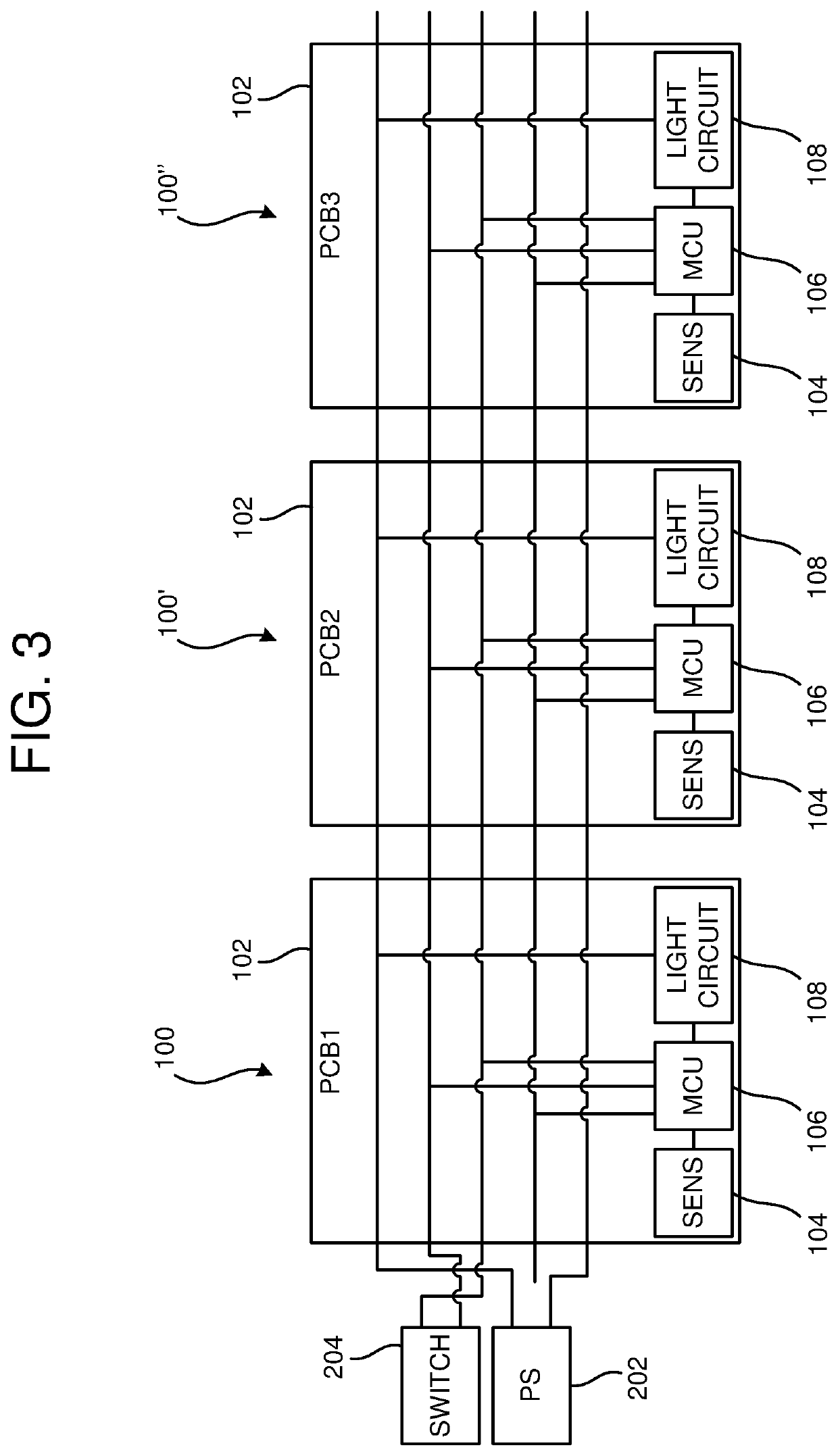
This patent describes a way to make a small and simple illumination system by adding sensor and illumination circuitry to a printed circuit board. This allows for easy assembly and scaling of the system by adding more printed circuit boards. The system can also be controlled by external switches or data computational elements.

Problems solved by technology

However, the size of the packaging to implement this functionality can be large because the necessary sensors may require special power requirements, lensing, and / or placement that is independent of a circuits that controls the lighting element.

Method used


Image

  • Circuit board with sensor controlled lights and end-to-end connection
  • Circuit board with sensor controlled lights and end-to-end connection
  • Circuit board with sensor controlled lights and end-to-end connection

Examples


Embodiment Construction

[0016]While this invention is susceptible of embodiments in many different forms, there is shown in the drawings, and will herein be described in detail, a preferred embodiment of the invention with the understanding that the present disclosure is to be considered as an exemplification of the principles of the invention and is not intended to limit the broad aspect of the invention to embodiments illustrated. As used herein, the term “present invention” is not intended to limit the scope of the claimed invention and is instead a term used to discuss exemplary embodiments of the invention for explanatory purposes only.

[0017]The present invention relates broadly to printed circuit boards with sensor controlled illumination units and end-to-end connection capabilities. For example, a printed circuit board (PCB) of the invention generally includes a sensor module, a microcontroller module, an illumination circuit, a power management module, an electrical circuit adapted to provide elect...


PUM


Abstract

Printed circuit boards with sensor controlled illumination units and end-to-end connection capabilities. For example, a lighting element, sensor / detector, and computational control element are implemented on a printed circuit board. The printed circuit board also includes end-to-end connection terminals that allow multiple printed circuit boards to be operably coupled together in an end-to-end manner. This provides a scalable system that can be modularized to a base unit for installation in various packages, orientations, or environments.

Description

TECHNICAL FIELD OF THE INVENTION[0001]The present invention relates generally to printed circuit boards with end-to-end connection capabilities, and more particularly to printed circuit boards with sensor controlled illumination units and end-to-end connection capabilities.BACKGROUND OF THE INVENTION[0002]The desire to activate and deactivate lighting elements based on detection of events in a surrounding environment is common. In general, lighting elements can be connected to sensors or detectors, and illuminate an area or object in response to an environmental signal, such as motion, sound, heat, humidity, etc. However, the size of the packaging to implement this functionality can be large because the necessary sensors may require special power requirements, lensing, and / or placement that is independent of a circuits that controls the lighting element.[0003]In other examples, the lighting element is physically decoupled from the sensor, and the lighting element and sensor are on s...

Claims


Application Information

Patent Timeline
Patent Type & Authority Applications(United States)
IPC IPC(8): H05B47/11F21V23/04F21V23/00
CPCH05B47/11F21V23/0464F21V23/005F21V23/0457F21V23/0492F21V23/0442H05B47/105F21Y2115/10H05B47/18Y02B20/40H05B47/115F21S2/005F21V23/0471F21V23/06
Inventor KUTER-ARNEBECK, OTTOLEOWEIR, NICHOLAS H.SCHULZ, BENHANSEN, STEVEN K.KAHL, ROBERT F.
Owner SNAP ON INC
Why Eureka
Eureka Blog
Learn More