
Switchable rocker arm with improved switching response time

a rocker arm and response time technology, applied in the field of rocker arms, can solve the problems of increasing the overall affecting the operation and the response time of the lock pin can be sensitive, so as to minimize the packaging size of the rocker arm and the effect of oil flow

Active Publication Date: 2017-01-03
DELPHI TECH IP LTD
View PDF6 Cites 1 Cited by
  • Summary
  • Abstract
  • Description
  • Claims
  • Application Information

AI Technical Summary

Benefits of technology

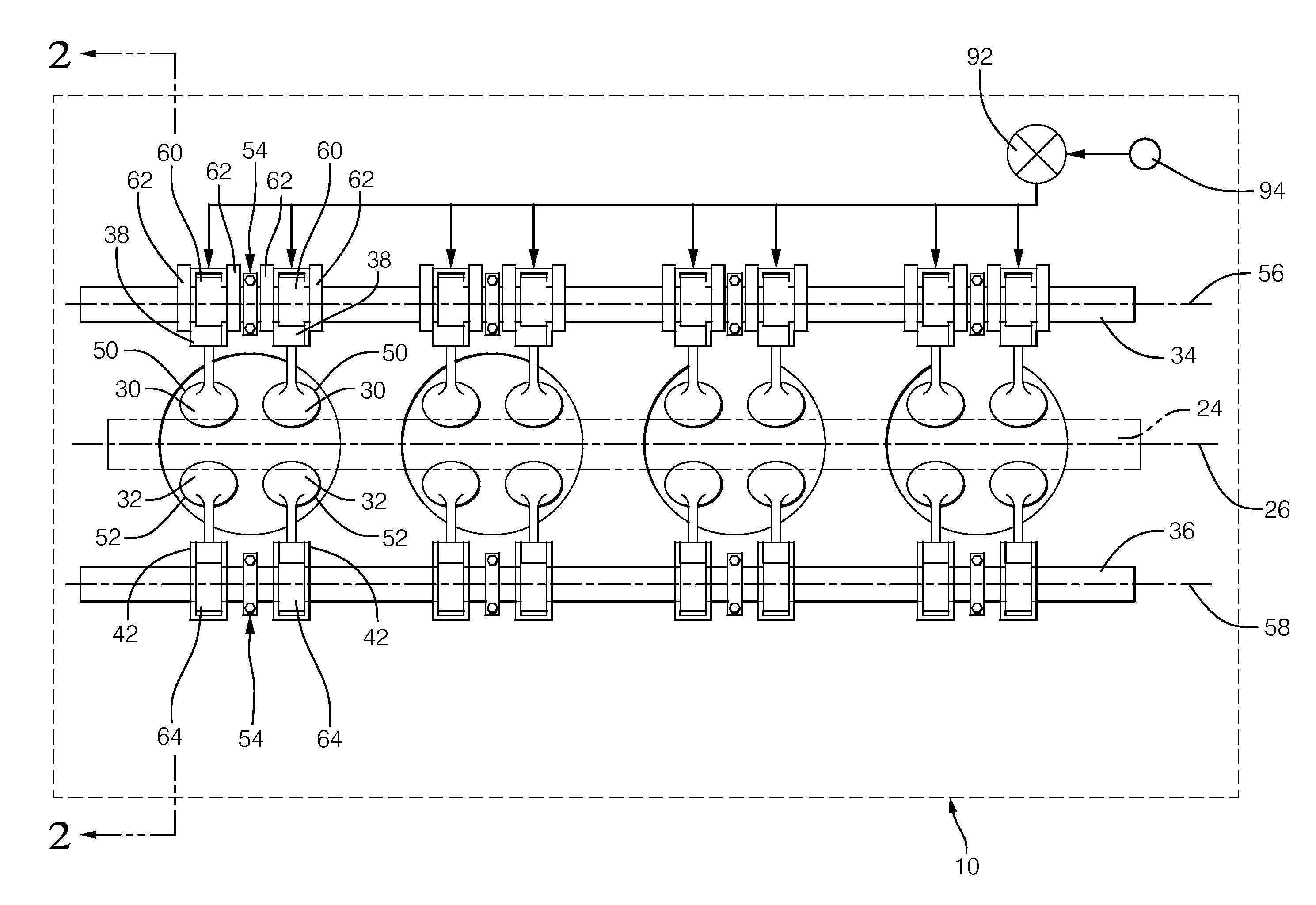
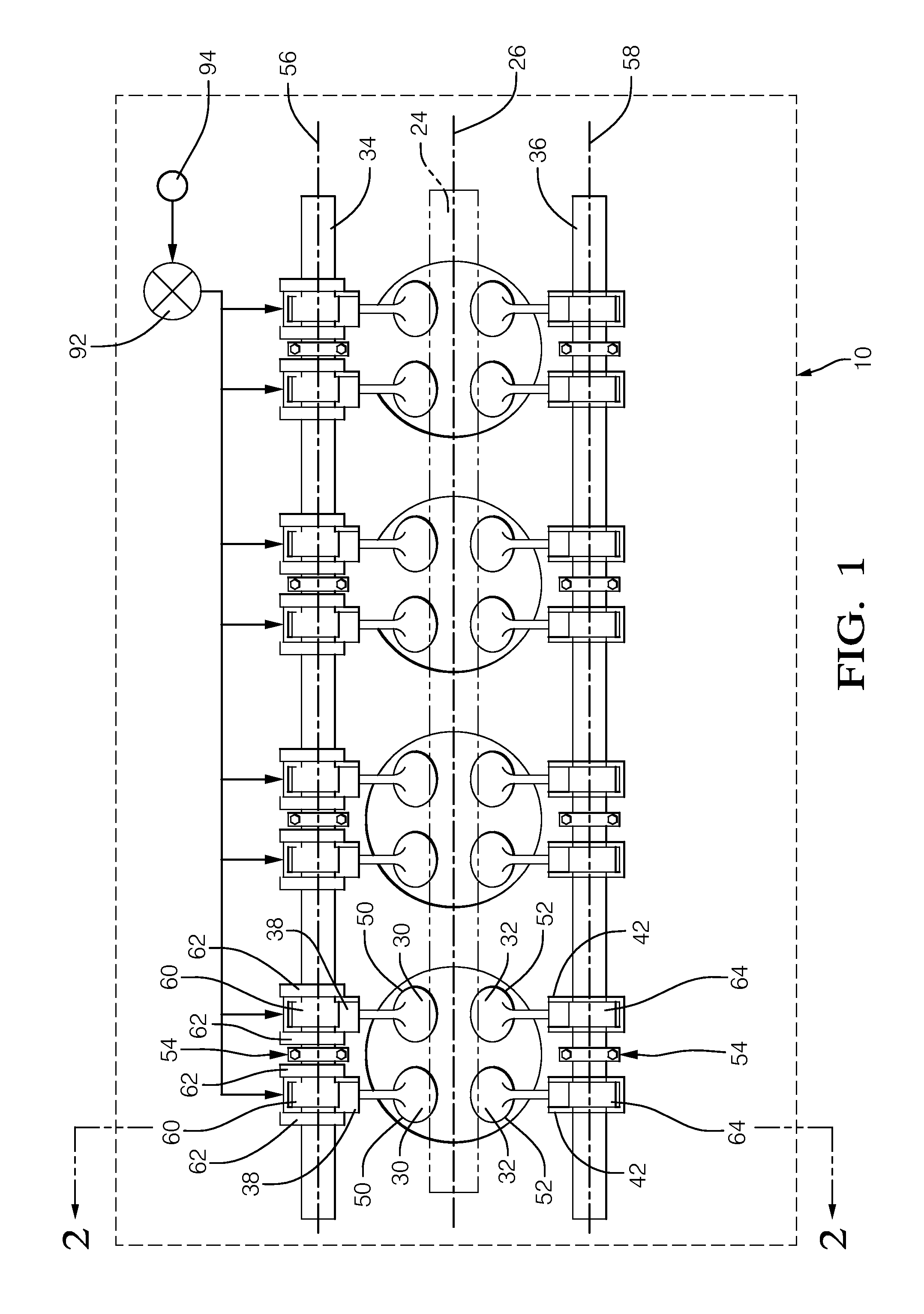
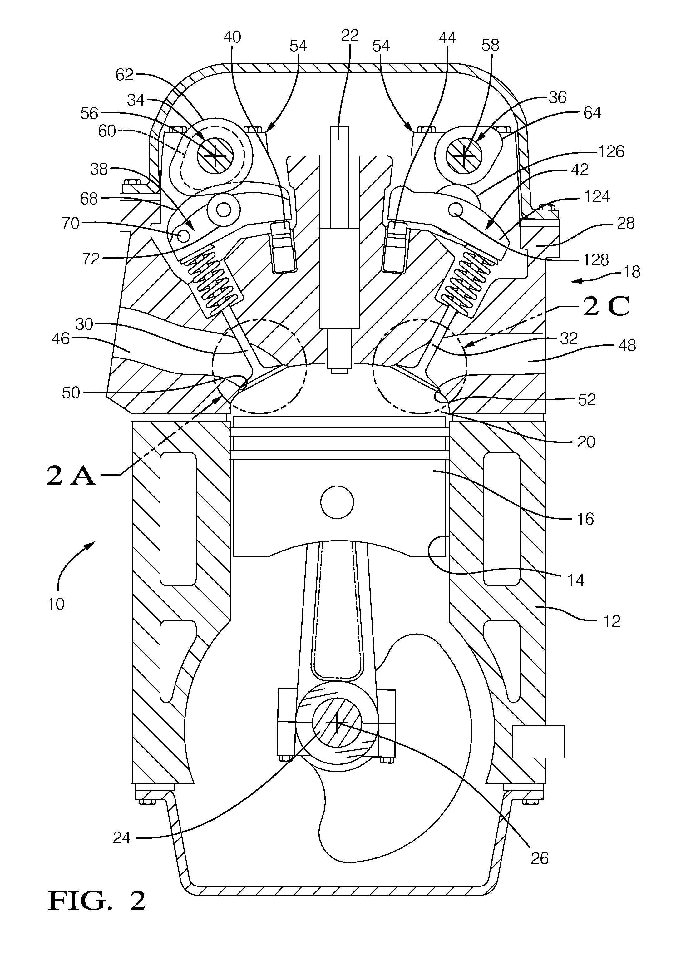
This patent describes a device called a rocker arm that helps move a valve in an internal combustion engine. The rocker arm has a part called a follower that moves along with a cam in the engine. The rocker arm also has a lock pin that can move between two positions to control the movement of the follower. The rocker arm has a passage that allows oil to flow through it to move the lock pin quickly. This design makes the rocker arm work more efficiently with less oil, while still being effective at controlling the movement of the valve.

Problems solved by technology

However, due to packaging constraints of the rocker arm, it may not be possible to increase the diameter of the oil passage without also increasing the size of other features of the rocker arm which also increases the overall packaging size of the rocker arm.
Furthermore, the response time of the lock pin can be sensitive to the circumferential orientation of the lash adjuster in the internal combustion engine due to misalignment of an oil inlet of the lash adjuster with the oil supply of the internal combustion engine.

Method used


Image

  • Switchable rocker arm with improved switching response time
  • Switchable rocker arm with improved switching response time
  • Switchable rocker arm with improved switching response time

Examples


first embodiment

[0030]In a first embodiment as shown in FIG. 4, rocker arm oil passage 90 is elongated in a circumferential direction around lock bore third section 104. As shown, rocker arm oil passage 90 is non-circular and includes opposing semicircular end walls 116 which are connected by opposing substantially straight sidewalls 118. Rocker arm oil passage 90 may be formed, by way of non-limiting example only, by milling, electrical discharge machining (EDM), or punching. In this way, rocker arm oil passage 90 allows the length of lock bore third section 104 along axis 98 to be minimized while allowing sufficient flow of oil through rocker arm oil passage 90 to minimize the time taken to engage or disengage lock pin 86 with high lift follower 68. Rocker arm oil passage 90 also decreases the sensitivity of the circumferential orientation of the intake lash adjuster 40 in internal combustion engine 10. While rocker arm oil passage 90 has been shown and described as including opposing semicircula...

second embodiment

[0031]In a second embodiment as shown in FIG. 5, rocker arm oil passage 90 is replaced with rocker arm oil passage 90′ which is defined by two oil passages 120 that may each be cylindrical as shown. Oil passages 120 are spaced circumferentially about lock bore third section 104, and consequently, rocker arm oil passage 90′ is elongated in a circumferential direction around lock bore third section 104. Like rocker arm oil passage 90 described above, rocker arm oil passage 90′ allows the length of lock bore third section 104 along axis 98 to be minimized while allowing sufficient flow of oil through rocker arm oil passage 90 to minimize the time taken to engage or disengage lock pin 86 with high lift follower 68. However, since rocker arm oil passage 90′ is defined by oil passages 120 that are cylindrical, rocker arm oil passage 90′ may be formed, for example only, by drilling which may be less complex and less costly. While rocker arm oil passage 90′ has been described and illustrate...


PUM


Abstract

A rocker arm includes a follower which follows a first lobe of a camshaft and is mounted to a rocker arm body; a lock pin that is selectively moveable in a lock bore between a first position and a second position in order to prevent relative movement between the rocker arm body and the follower in one of the first position and the second position and to permit relative movement between the rocker arm body and the follower in the other of the first position and the second position; and a rocker arm oil passage in fluid communication with the lock bore for communicating oil therethrough to move the lock pin between the first position and the second position. The rocker arm oil passage is elongated in a circumferential direction relative to the lock bore.

Description

TECHNICAL FIELD OF INVENTION[0001]The present invention relates to a rocker arm for transmitting opening and closing motion from a camshaft to a combustion valve of an internal combustion engine; more particularly to such a rocker arm which is switchable between a high lift mode and a low lift mode; and even more particularly to an oil passage for supplying and draining oil to and from a locking mechanism which switches the rocker arm between the high lift mode and the low lift mode.BACKGROUND OF INVENTION[0002]It is known in the art of internal combustion engines to provide variable valve actuation devices which are switchable between a low lift mode and high lift mode, thereby opening a combustion valve, for example an intake valve, to a low lift and a high lift respectively. One such variable valve actuation device is disclosed in United States Patent Application Publication No. US 2009 / 0078225 to Hendriksma, hereinafter referred to as Hendriksma, the disclosure of which is incor...

Claims


Application Information

Patent Timeline
Patent Type & Authority Patents(United States)
IPC IPC(8): F01L1/34F01L1/18
CPCF01L1/18F01L1/185F01L1/2405F01L13/0036F01L2001/0537F01L2001/186F01L2810/02
Inventor LEE, JONGMINTAWAF, CYNTHIA A.JERMY, IAN R.NABER, GREGORY J.
Owner DELPHI TECH IP LTD
Learn More