Rotary cutting tool

Pending Publication Date: 2022-08-11
OSG
View PDF0 Cites 0 Cited by
  • Summary
  • Abstract
  • Description
  • Claims
  • Application Information

AI Technical Summary

Benefits of technology

The present invention provides a rotary cutting tool with improved coolant supply for cutting edges. The tool includes a shank portion with coolant-guide recessed grooves that are positioned in the outer circumferential surface of the shank portion and are spaced apart from each other. The recessed grooves have a flat cross-sectional shape and are designed to guide coolant from the shank portion to the connecting portion of the tool. The recessed grooves are also designed to minimize turbulence in the coolant flow and ensure a sufficient supply of coolant to the cutting edge of the blade portion. The tool has improved coolant supply without compromising rigidity or centering accuracy, and can effectively suppress cutting-edge wear and obtain cutting efficiency.

Problems solved by technology

Thus, since the cross sectional area of the coolant guide hole is limited, the supply of the coolant is limited due to resistance to flow of the coolant in the coolant guide hole, so that there is a case in which it is difficult to supply the coolant to the cutting edge at a sufficient rate.
Such an inconvenience is more pronounced where the diameter of the blade portion of the rotary cutting tool is small.

Method used


Image

  • Rotary cutting tool
  • Rotary cutting tool
  • Rotary cutting tool

Examples


embodiment 1

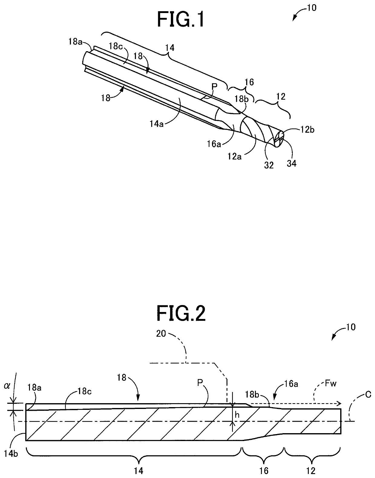
[0033]FIG. 1 shows a rotary cutting tool 10 according to an embodiment of the present invention. The rotary cutting tool 10 is made by cutting a single material such as tool steel or cemented carbide, and includes a blade portion 12 including a cutting edge provided therein, a cylindrical-shaped shank portion 14 having a diameter larger than a diameter of the blade portion 12, and a connecting portion 16 having a tapered outer circumferential surface 16a and connecting the blade portion 12 and the shank portion 14, such that the blade portion 12, the shank portion 14 and the connecting portion 16 are integral with one another. The blade portion 12 includes a peripheral cutting-edge portion 32 provided in an outer circumferential surface 12a of the blade portion 12 and an end cutting-edge portion 34 provided in an end surface 12b of the blade portion 12. That is, the blade portion 12 is to be used as an endmill or a thread mill, for example. In the drawings except FIG. 1, the blade p...

embodiment 2

[0050]There will be described other embodiments of this invention. The same reference signs as used in the above-described embodiment will be used in the following embodiments, to identify the practically corresponding elements, and descriptions thereof are not provided.

[0051]FIG. 7 is a view corresponding to the view of FIG. 2 and showing a cross section of a rotary cutting tool 50 according to another embodiment of the present invention. As shown in FIG. 7, the rotary cutting tool 50 is substantially the same as the rotary cutting tool 10, although being different from the rotary cutting tool 10 in that the groove bottom 18c of each of the coolant-guide recessed grooves 18 has an arc shape, rather than the polyline shape, in the groove-depth regional-change position, wherein the arc shape has a predetermined radius R1 of curvature.

[0052]In the rotary cutting tool 50 according to this embodiment, the groove bottom 18c of each of the coolant-guide recessed grooves 18 has the arc sha...

embodiment 3

[0053]FIG. 8 is a view corresponding to the view of FIG. 2 and showing a cross section of a rotary cutting tool 60 according to another embodiment of the present invention. As shown in FIG. 8, the rotary cutting tool 60 is substantially the same as the rotary cutting tool 10, although being different from the rotary cutting tool 10 in that the groove bottom 18c of each of the coolant-guide recessed grooves 18 has an arc shape, rather than the polyline shape, in the groove-depth regional-change position P, wherein the arc shape has a predetermined radius R1 of curvature, and in that each of the coolant-guide recessed grooves 18 has a groove bottom shape such that the distance h from the rotary axis C is gradually reduced from the groove-depth regional-change position P to the terminal end 18b (namely, the groove bottom 18c of each of the coolant-guide recessed grooves 18 has an inclined surface extending from the groove-depth regional-change position P to the terminal end 18b, wherei...


PUM


Abstract

A rotary cutting tool includes: a blade portion; a shank portion having a diameter larger than a diameter of the blade portion; and a tapered connecting portion connecting the blade portion and the shank portion. The shank portion includes a plurality of coolant-guide recessed grooves provided in its outer circumferential surface. Each of the coolant-guide recessed grooves has a groove depth and a groove width that is larger than the groove depth. Each of the coolant-guide recessed grooves has a groove bottom that is shaped such that the groove depth is reduced as the each of the coolant-guide recessed grooves extends from its start end toward a groove-depth regional-change position in which a tendency of change of the groove depth is changed.

Description

TECHNICAL FIELD[0001]The present invention relates to a rotary cutting tool including guide grooves for guiding a coolant, and more particularly, to a technique for efficiently cooling a cutting edge so as to suppress progress of cutting-edge wear, without reducing rigidity of the rotary cutting tool.BACKGROUND ART[0002]A rotary cutting tool, which is provided with a blade portion having a relatively small diameter of, for example, 10 mm or less, includes a shank portion having a diameter larger than the diameter of the blade portion. Since such a rotary cutting tool is driven and rotated at a relatively high speed, wear of cutting edge of the blade portion is large. For suppressing progress of the cutting-edge wear, a coolant is supplied to the cutting edge of the blade portion through the shank portion so as to cool the cutting edge. A milling tool disclosed in Patent Document 1 is an example of such a rotary cutting tool.[0003]In the disclosed milling tool, a coolant guide hole i...

Claims


Application Information

Patent Timeline
IPC IPC(8): B23C5/28
CPCB23C5/282B23C5/281B23C5/10B23B31/005B23B2231/0264
Inventor OSAWA, JIROYODA, TOMONORITANAKA, YUSUKE
Owner OSG
Why Eureka
Try Eureka