Apparatus and Method for Producing Printed Products

Active Publication Date: 2022-08-11
MULLER MARTINI HLDG
10 Cites 0 Cited by

AI-Extracted Technical Summary

Problems solved by technology

Also unnecessary are the connecting locations between pipe sections, ...

Method used

[0041]The casing 63 on the right side of the sheet feeder 60 is shown in FIG. 2 in a sectional view below the local display and operating unit 37, to allow a view of the blower 65. As can be seen in FIG. 3, the blower 65 shown therein is embodied as compact radial blower which has a maximum overpressure of only 0.005 to 0.01 bar on the side of the air exit and delivers a volume flow of 1 to 5 m3/minute. Also conceivable is the use of other types of blowers or fans, such as impeller fans, axial fans, ventilators without rotors, pipe ventilators or blowers with a Venturi pipe. The blower 65 is attached with a fastening element 66 to the frame 61 and is connected via control lines 67 to the local display and operating unit 37 or the control unit 35. A fastening element 66 which can be attached or detached without tools can be selected to dismantle the blower 65 easily and quickly, for example for cleaning purposes. Accordingly, the control lines 67 can be connected via a detachable plug connection to the blower 65, for an easy and quick decoupling.
[0049]FIG. 6 shows a view from below of the distribution channel 70 and differently designed blast pipes 71, 100, 102. Shown on the left is the blast pipe 71 with rectangular flow cross section 72, which is also shown in FIGS. 3 and 4. On the right side, a blast pipe 100 is shown with a round flow cross section 101 which can be manufactured particularly easily through bending of the blast pipe 100 on the outlet side at the desired angle. A different blast pipe 102 with flow-optimized geometry is shown in FIG. 6, between the two blast pipes 71, 100. The blast pipe 102 has a slot-type outlet opening 103, with a rather flat but widely spread apart blast air stream 104 exiting therefrom and flowing in different directions 75. An outlet opening 73, 103 can also be embodied as elongated slot in the distribution channel, which extends over the complete length of the distribution channel...

Abstract

An apparatus for producing printed products such as books, magazines, brochures, catalogues or the like comprises several connected devices for the processing of printed sheets. The printed sheets are admitted with blast air via at least one air supply in order to change or maintain their position. At least two of the connected devices are respectively provided with at least one blower for generating blast air. The blast air can be used in the respective device. The blowers are connected to a control unit of the apparatus so that the blast air generated by the blowers can be controlled as needed.

Application Domain

Function indicatorsBook making processes +3

Technology Topic

Process engineeringConnected device +5

Image

  • Apparatus and Method for Producing Printed Products
  • Apparatus and Method for Producing Printed Products
  • Apparatus and Method for Producing Printed Products

Examples

  • Experimental program(1)

Example

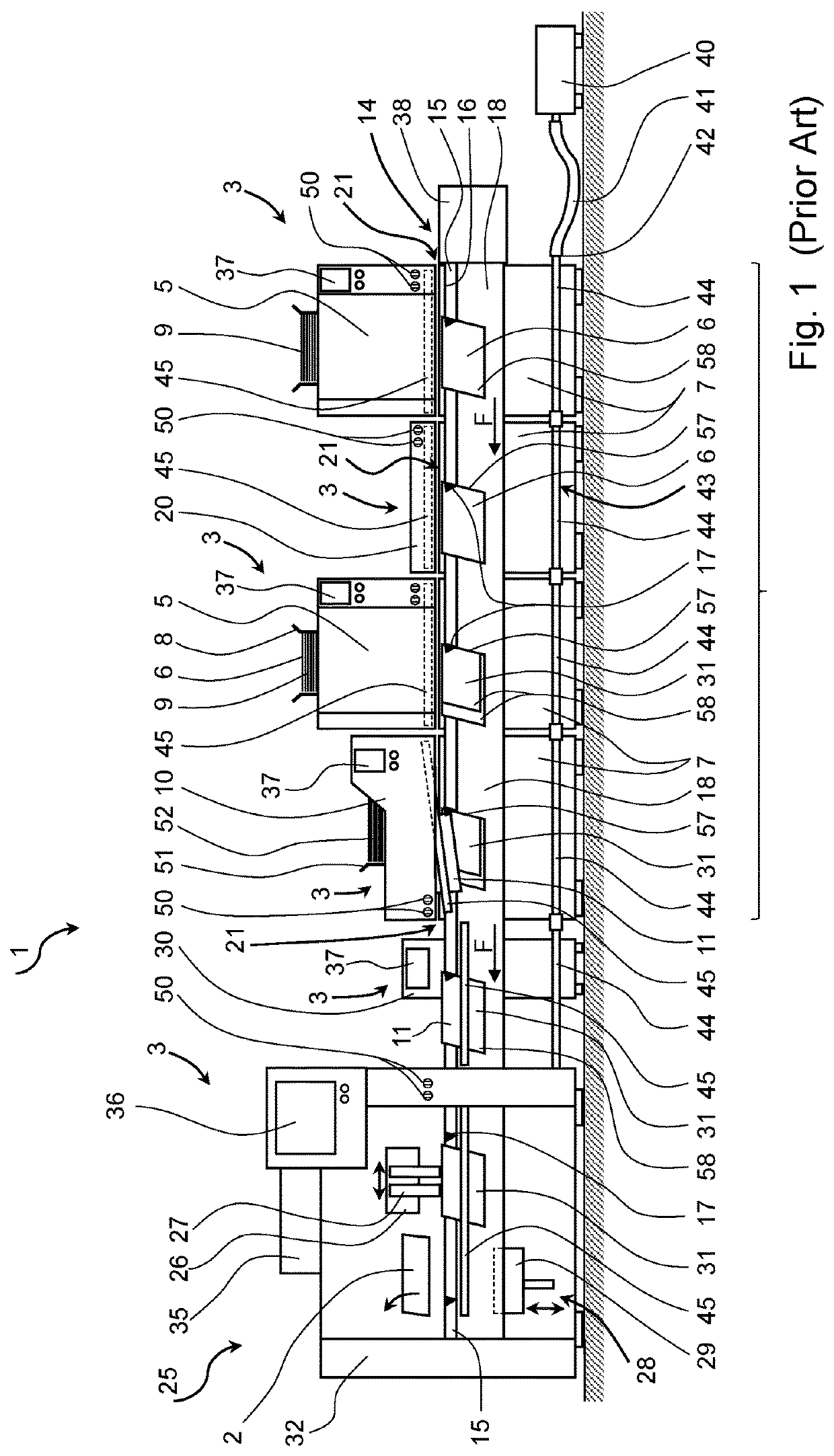
[0031]FIG. 1 schematically shows an apparatus 1 according to the prior art, embodied as a gathering and stapling device, for producing printed products 2. A gathering and stapling device is comprised of individual devices 3 which are connected, for example mechanically, pneumatically, electrically, and/or via control lines. Sheet feeders 5 and other devices 3 for processing printed sheets 6 are arranged side-by-side along a gathering section 4. Conveying elements 14 transport the printed sheets 6 and all intermediate products up to the finished printed product 2 with the apparatus 1 to the location where they are transferred to a following apparatus. In the field of post-print processing, the terms processing or handling refer to all operating steps relating to the printed sheets, for example transporting, conveying, rotating, turning, orienting, fixing, clamping, opening, closing, measuring, testing, counting, identifying, printing, stapling, applying adhesive, gluing, stamping, cutting, milling, grinding, pressing, forming, folding, redirecting, separating, grooving, perforating, inserting, placing on top, gathering, sorting, stacking, packaging, heating, cooling, and the like. The sheet feeders 5 are attached so as to be detachable to machine frames 7, so that their position along the gathering section 4 can be changed. The example in FIG. 1 shows two sheet feeders 5, mounted on the four machine frames 7, for processing sheet stacks 9 that are positioned flat inside sheet hoppers 8, as well as a sheet feeder 5 embodied as a fold feeder 10 for processing non-folded covers 11. A conveying element 14, which circulates below all the sheet feeders 5 and is embodied as gathering chain 15, comprises a ridge line 16 as for a roof and is provided with regularly spaced-apart carriers 17 for transporting the printed sheets 6. Below the gathering chain 15, guide sheets 18 adjoin the ridge line 16 of the gathering chain 15. Gathering sections are furthermore known from the prior art which comprise a gathering chain 15 without guide sheets 18.
[0032]An empty space remains for an additional sheet feeder 5 between the two sheet feeders 5. The missing sheet feeder 5 was removed, for example for maintenance operations, and a blind cover 20 attached in its place to the machine frame 7. The blind cover 20 covers mechanical and electrical points of intersection 21 on the machine frame 7, which are needed for fastening the sheet feeders 5. For safety reasons, the blind cover 20 extends past the gathering chain 15 positioned below it.
[0033]Downstream of the fold feeder 10, a stapling machine 25 is arranged which comprises an oscillating stapling device 26 with two stapling heads 27 and a delivery 28. With the aid of an up and down movable ejector 29, the stapled printed products 2 in the delivery 28 are lifted off the gathering chain 15 and are supplied to a further processing device that is not shown, for example to a trimmer. Between the last sheet feeder 6 or the fold feeder 10 in conveying direction F of the gathering chain 15 and the stapling device 25, a quality control unit 30 is arranged at the rear of the gathering chain 15. This unit, for example, serves to measure the thickness of a printed sheet stack 31, gathered so as to be positioned astride the gathering chain 15, and to check the position of the individual printed sheets 6 or the stack 11.
[0034]The gathering and stapling machine comprises a control unit 35, arranged inside a casing 32 of the stapling device 25. This control unit is connected to a central control unit 36 which is also attached to the stapling device 25 and contains local display and operating units 37, as well as non-depicted sensors and operating and adjustment elements for the devices 3.
[0035]A non-depicted drive device and a first deflection unit for the gathering chain 15 is provided inside the casing 32 of the stapling device 25, in the region of the delivery 28. At the start of the gathering section 4, a second deflection unit as well as a tensioning station for tensioning the gathering chain 15 are arranged below a cover 38, shown in FIG. 1.
[0036]A blast air source 40, embodied as compressor, which supplies the gathering and stapling device with blast air is shown to the right of the gathering and stapling device. Larger and/or several compressors are required for long gathering and stapling devices comprising numerous sheet feeders 5. To protect operating personnel from noise emissions of the compressors, these are in part installed in separate rooms. The blast air which is compressed to 1 to 1.5 bar overpressure is connected via suitable hoses 41 or pipes to a connecting location 42 for a blast air system 43 of the gathering and stapling machine. The blast air system 43 is provided in the area of the gathering section 4 with pipe sections 44, which are connected to each other and to the respective machine frame 7. With their large flow cross section and a length that extends nearly the complete length of the gathering and stapling machine, the blast air system 43 with its pipe sections 44 functions as blast air storage. From pipe segments 44 of a machine frame 7, a non-depicted blast air line respectively extends to a point of intersection 21 where a sheet feeder 5, a fold feeder 10, or the blind cover 20 is respectively fitted onto the machine frame 7. Blast-air lines which are not shown herein and are located inside the sheet feeders 5, the fold feeders 10, or the blind cover 20 conduct the blast air from the point of intersection 21 to an air supply 45. The air supply 45 is arranged above and on both sides of the gathering chain 15, approximately parallel to the conveying direction F for a printed product 6 or the printed-product stack 31. The air supply 45 is composed of two cylindrical pipes with several exit openings, distributed over its length and embodied as bores with a diameter of 0.5 to 2 mm, from which the air flows. The pipes for the air supply 45 are attached to the sheet feeder 5 or the machine frame 7, so as to rotate around their longitudinal axes. The direction of the outflowing blast air can thus be changed. With the aid of flow-control valves 50, which can be embodied as shut-off valves, the volume flow of the blast air can be adjusted manually and individually along the gathering section 4, in the region of the respective sheet feeder 5, the fold feeder 10, or the blind cover 20, either before or behind the gathering chain 15. In the region of the stapling device 25, as well as between the last machine frame 7 of the gathering section 4 and the stapling device 25, an air supply composed of pipes 45 with exit openings and flow-control valves 50 is arranged for regulating the blast air, similarly as in the region of the sheet feeders 5.
[0037]For producing printed products 2, stacks of folded printed sheets 6 are inserted according to the prior art into sheet hoppers 8 of the sheet feeders 5. Non-folded sheets 52 are placed into a sheet hopper 51 of the fold feeder 10 which is attached according to FIG. 1 at the end of the gathering section 4 to the machine frame 7. The first sheet feeder 5 uses a withdrawing drum 55, shown schematically in FIGS. 2 and 3, for withdrawing the lowest printed sheet 6 of the sheet stack 9 inserted into the sheet hopper 8 and conveys this sheet in the direction of the gathering chain 15. The printed sheet 6 is transferred by the withdrawing drum 55 to two opening drums 56. The opening drums 56 open the printed sheet 6 and deposit it on the gathering chain 15 moving below, such that the fold of the printed sheet 6 rests on the ridge 16. The opened sides of the printed sheet 6 rest on the guide sheets 18. With gathering chains without guide sheets 18, the printed sheets 6 are centered with their fold on the gathering chain 15 and the opened sides hang vertically downward beside the gathering chain 15. The opening drums 56 and the withdrawing drum 55, also called separating drum, comprise along the circumference non-depicted controllable grippers and/or vacuum suction cups for holding, accelerating and opening the printed sheets 6. Blast air is used to securely deposit the opened printed sheet 6 onto the gathering chain 15 that moves continuously in conveying direction F, even with higher production speeds or when using thinner paper.
[0038]Each additional sheet feeder 5 deposits the separated out printed sheets 6 onto the printed sheets 6 already positioned straddling on the gathering chain 15, thus forming several printed sheet stacks 31 which are conveyed one behind the other on the conveying chain 15. The fold feeder 10 frequently places a sheet 52 that is folded to form an envelope 11 on top of the printed sheet stack 31. Following the depositing onto the gathering chain 15 or the printed sheet stack 31, each printed sheet 6 or envelope 11 is slowed down slightly with the aid of braking elements, not shown, such as drag springs or brushes, so that a trailing edge 57 of the printed sheets 6 or the envelope 11 comes to rest against the following carrier 17. All gathered printed sheets 6 or the envelope 11 of the printed sheet stack 31, which can differ as to format, number of pages, type of paper and the like, consequently have a joint trailing edge 57. During the transport of a printed paper stack 31 on the gathering chain 15, there is danger that a still loose printed sheet 6 or envelope 11 is picked up by the movement air or an airflow and is displaced relative to the associated printed sheet stack 31 or is even lifted off partially or totally from the gathering chain. The leading free edges 58 of a printed sheet 6, positioned on the bottom, are frequently bent by the movement airflow toward the outside or the back. If a following printed sheet 6 or envelope 11 is deposited thereon, the bent edge can sometimes remain in the printed sheet stack 31, thus strongly reducing the quality of the finished printed product 2. Owing to the air supply 45 that is effective on both sides of the gathering chain and extends over the length of the gathering section 4 to the delivery 28, the above-mentioned blast air is utilized as well. For example, printed sheet stacks 31 transported on the gathering chain 15, for which the top printed sheet 6 has a large-format or is composed of thin and lightweight paper, require more blast air than printed sheet stacks 31 covered by a heavy or rigid envelope 11. The amount of blast air is manually adjusted via the flow-control elements 50, so that the correct amount of blast air flows from the air feed 45 in each region, corresponding to the production speed and the composition of the sheet stack 31. Not enough blast air can favor the aforementioned undesirable effects. Too much blast air can cause the printed sheets 6 to be ragged instead of supporting the change in position for the printed sheets and maintaining the desired position for the printed sheets 6 on the gathering chain 15. In the region of the quality control unit 30 and the stapling device 25, the air feed 45 is not arranged above the gathering chain 15, as is the case along the gathering section 4, but is arranged preferably at the level of the guide sheets 18. The air feed 45 can optionally be embodied such that it is adjustable, relative to the height and the distance to the gathering chain 15 and/or the guide sheets 18. The pipes for the air feed 45 can function as guide elements and can contribute to a secure and trouble-free transport of the printed sheet stacks 31 between gathering section 4 and stapling device25, even with little or no blast air flowing out. The lower installation of the air feed 45, relative to the gathering section 4, is possible since downstream of the gathering section no additional printed sheets 6 or folded envelopes 11 are deposited opened or folded on the printed sheet stack 31.
[0039]Following the gathering operation on the gathering section 4, the printed sheet stacks 31 are checked in the quality control 30 by measuring the thickness and determining their completeness. Any printed sheets 6 with a fold that is not positioned precisely on the ridge 16 can also be detected by the quality control. Flawed printed page stacks 31 are not stapled in the stapling device 25 and are removed following the delivery. All other stacks 31 are provided in the stapling device 26 with the desired number of staples. In the delivery 28, the stapled printed sheet stacks 31 or the printed products 2 are removed from the gathering chain 15 with the ejector 29 and are supplied as described in the above, for example to a trimmer.
[0040]FIG. 2 schematically shows a device 3, embodied as sheet feeder 60, for an inventive apparatus 1. The withdrawing drum 55 and the opening drums 56 are positioned inside a frame 61 as for the sheet feeders 5 shown in FIG. 1. The printed sheets 6 are inserted in a manner known per se as a vertically positioned sheet stacks 9 or, as shown in FIGS. 1 and 2, as a horizontal sheet stack into the sheet hopper 8. The sheet feeder 60 is connected via an intersection 62 to the machine frame 7. For this, the frame 61 of the sheet feeder 60 is fitted onto the machine frame 7 and is detachably mounted thereon. Lines of the sheet feeder 60 that are not shown herein and are used, for example, for compressed air, control signals, and electrical power, are connected via the intersection 62 to lines of the apparatus 1. However, in contrast to the intersection 21 of the sheet feeder 5 according to the prior art, the intersection 62 of the sheet feeder 60 does not have a connection for blast air. In addition to the local display and operating unit 37, numerous drive elements, bearing members, switching and control elements are attached to the frame 61, which are not shown herein and in part are covered by casings 63.
[0041]The casing 63 on the right side of the sheet feeder 60 is shown in FIG. 2 in a sectional view below the local display and operating unit 37, to allow a view of the blower 65. As can be seen in FIG. 3, the blower 65 shown therein is embodied as compact radial blower which has a maximum overpressure of only 0.005 to 0.01 bar on the side of the air exit and delivers a volume flow of 1 to 5 m3/minute. Also conceivable is the use of other types of blowers or fans, such as impeller fans, axial fans, ventilators without rotors, pipe ventilators or blowers with a Venturi pipe. The blower 65 is attached with a fastening element 66 to the frame 61 and is connected via control lines 67 to the local display and operating unit 37 or the control unit 35. A fastening element 66 which can be attached or detached without tools can be selected to dismantle the blower 65 easily and quickly, for example for cleaning purposes. Accordingly, the control lines 67 can be connected via a detachable plug connection to the blower 65, for an easy and quick decoupling.
[0042]A distribution channel 70 for blast air is arranged inside the frame 61, in the region of the opening drum 56. The distribution channel 70 adjoins an air outlet 68 of the blower 65. Blast pipes 71 are arranged spaced-apart on the distribution channel 70 in place of the small bores, as described for the aforementioned pipes for the air supply 45 according to the prior art. The blast air is conducted from the blower 65 via the distribution channel 70 and through the blast pipes 71, either to the region where a printed sheet 6 is supported for changing its position during the depositing onto the gathering chain 15, or the blast air is conducted to a region along the gathering section 4 where this blast air serves to maintain the position of a printed sheet 6 or an envelope 11, previously deposited on the gathering chain 15, and the guide sheets 18 during the transport. The blast pipes 71 have a continuous, relatively large flow cross section 72 throughout, as shown in FIG. 4, which can range from 10 to 2000 mm2, advantageously from 50 to 400 mm2, especially preferred from 100 to 200 mm2. An exit opening 73 of the blast pipe 71 also has a flow cross section in the range of the aforementioned flow cross section 72. The blast pipes 71 and the exit opening 73 are embodied such that a blast air stream 74 exits in a desired direction 75, has a desired scattering angle 76, and exhibits the desired flow speed by having a corresponding flow cross section 72. The blast air stream 74 with low flow speed, but higher volume flow is intended to exert the desired impulse force onto the printed sheet 6. The impulse force generated with the inventive apparatus 1 is comparable to the impulse force that can be achieved according to the prior art with blast air that is compressed to 1 to 1.5 bar overpressure and small exit openings in the distribution channels.
[0043]The following mathematical formula shows how a change in the air mass m or the speed {right arrow over (v)} affects the impulse force {right arrow over (p)}:
{right arrow over (p)}=m·{right arrow over (v)}
[0044]If the speed of the blast air is reduced, the air mass which is directly connected to the volume of blast air must correspondingly be increased to obtain an identical impulse force.
[0045]FIG. 3 schematically shows a view from the side of the sheet feeder 60, for which the frame 61, the casings 63 and the drive and positioning components arranged below the casings 63 were mostly blanked out. The viewing direction corresponds to the conveying direction F of the gathering chain 15. It is obvious that before and after the gathering chain respectively one blower 65 is arranged in a sheet feeder 60, meaning left and right in FIG. 3, which is connected to respectively one distribution channel 70. Of course, both blowers 65 are connected to the local display and operating unit 37. As shown in FIGS. 2 & 3, the blowers 65 can be attached so as to be detachable with the fastening elements 66 to the frame 61 or can be attached directly to the distribution channels 70. It is conceivable that a blower 65 is connect to two or more distribution channels 70. It is furthermore conceivable that one distribution channel 70 is connected to two or more blowers 65 blowing the air with low pressure but high flow volume into the distribution channel 70. According to FIG. 4, the blast air generated by a blower—is blown with low overpressure into the distribution channel 70 that is connected to the blower 65. The distribution channels 70 have a flow cross section 77, for example ranging from 4 to 40 cm2. A high blast air volume can flow with low pressure from the exit openings 73 in the blast pipes 71 because of the large flow cross section 77 of the distribution channels 70 and the large flow cross section 72 of the blast pipes 71. The blast pipes 71 have generously dimensioned exit openings 73 as compared to the small bores in the pipes of the air supply 45 according to the prior art. Since each device 3 of the inventive apparatus 1 comprises one or several blowers that are connected to the distribution channels 70 and the blast pipes 71, the distribution channels 70 have a relatively short length. For a gathering and stapling machine with sheet feeder 60, for example, the distribution channels 70 have a length of only 40 to 100 cm. Depending on the requirements, more or fewer blast pipes 71 are arranged at the distribution channel with constant or differing spacing, relative to each other.
[0046]FIG. 4 shows an enlarged section of the region of the opening drum 56 for a sheet feeder 60, as represented in FIG. 3. The cross-sectional surface 77 of the distribution channel 70 is marked by hatching. The flow cross section 72 of a blast pipe 71 is also marked by hatching in FIG. 4. In addition to the herein shown rectangular-flow cross sections, round, oval and other shapes are also conceivable. The blast pipes 71 and their exit openings 73 are embodied such that they emit the blast air stream 74 at the most ideal location possible, in a desired direction 75 and with an optimum scattering angle 76. The amount or flow volume and thus also the speed of the blast air stream 74 flowing out is determined by the blower 65. The control 35 controls the blower 65 by changing the rotational speed of a motor 80 for the blower 65. Changing the volume flow at constant blower speed via an adjustable and controllable throttle valve, for example arranged in the region of the air exit 68 of the blower 65, is also conceivable.
[0047]The blower 65 comprises a casing 81, with the motor 80 and an impeller 82 positioned therein. The casing 81 is designed such that the impeller 82, driven by the motor 80 and provided with blades, suctions in the ambient air 84 via an inlet opening 83 (FIG. 2), compresses this air, and allows it to flow into the distribution channel 70 via the air outlet 68. Gathering and stapling machines and other apparatuses 1 for producing printed products 2 are oftentimes operated in an environment where the ambient air 84 contains a higher share of paper dust and other types of dust. Over time, the dust can be deposited on the impeller 82 of the blower 65, thus reducing the volume flow generated by the blower and its pressure. At the same time, the rotational speed, respectively the energy consumption, of the motor 80 increases during the acceleration of the impeller 82 as a result of the dust deposits. The increase in the speed or the current consumption can be detected via the control unit 35. If a threshold value that is defined in the control unit 35 is exceeded, the control unit 35 sends a warning to the central control unit 36 or the local display and operating units 37. The user of the apparatus 1 cleans the blower 65, for example by detaching the fastening element 66, removing the blower 65 from the sheet feeder 60, and using blast air to clean it. It is furthermore conceivable to arrange an air filter 85 at the intake opening 83 of the blower 65 which filters out the dust from the suctioned-in ambient air before it enters the blower 65. After a certain amount of time, the air filter 85 will be clogged with enough dust, so that it must be cleaned or replaced. FIG. 2, for example, shows a cleaning device 86 that is embodied as air nozzle 87. When activating a pneumatic valve 88, the air nozzle 87 blows the dust from the filter with the aid of compressed air stored in a compressed air reservoir 89. The pneumatic valve 88 is connected via a control line 90 to the local display and operating unit 37. The cleaning operation can be triggered automatically via the control unit 35, either as soon as it is detected that the filter 85 is clogged with dust or at specified intervals defined by the user. Alternatively, the user could also manually trigger the cleaning operation, if necessary, via the local display and operating unit 37 or another operating unit. It is furthermore conceivable that the dust is removed by a vibration element that is connected to the filter 85 or the casing 81 of the blower 65 and is triggered by one of the above-described methods.
[0048]FIG. 5 shows an alternative design for a blast pipe 71. This pipe has a flow-optimized geometry 95 which allows generating a nearly laminar flow of blast air in the blast pipe 71 up to the exit opening 73. The nearly laminar flow has the same flow direction over a total cross section 96, perpendicular to the flow direction, and is thus free of swirling and turbulence. As a result, the impulse force of the blast air stream 74 is increased with the same flow speed and the same volume flow. The blast pipe 71 with flow-optimized geometry 95 can be connected directly to the air exit 68 of the blower 65, as shown in FIG. 5. It is also conceivable that the blast pipe 71 with flow-optimized geometry 95 is connected directly to an also flow-optimized distribution channel 70. Of course, the distribution channel 70 and the blast pipes 71, branching off therefrom, can also be embodied as a single part or as several parts.
[0049]FIG. 6 shows a view from below of the distribution channel 70 and differently designed blast pipes 71, 100, 102. Shown on the left is the blast pipe 71 with rectangular flow cross section 72, which is also shown in FIGS. 3 and 4. On the right side, a blast pipe 100 is shown with a round flow cross section 101 which can be manufactured particularly easily through bending of the blast pipe 100 on the outlet side at the desired angle. A different blast pipe 102 with flow-optimized geometry is shown in FIG. 6, between the two blast pipes 71, 100. The blast pipe 102 has a slot-type outlet opening 103, with a rather flat but widely spread apart blast air stream 104 exiting therefrom and flowing in different directions 75. An outlet opening 73, 103 can also be embodied as elongated slot in the distribution channel, which extends over the complete length of the distribution channel or the device 3. Identical or different blast pipes 71, 100, can also be arranged spaced-apart on a distribution channel 70 of a device 3. Also conceivable is that identical or different blast pipes 71, 100, 102 are arranged at a different angle, relative to a horizontal and/or vertical plane, on the distribution channel 70 or that these can be changed by means of a manual or automatic adjustment device.
[0050]If and how much blast air is required with a device 3 for the processing of printed sheets 6 to ensure an uninterrupted operation and to produce high-quality printed products 2 depends on various factors and parameters, for example on the production speed. As a rule, the blast air requirement increases with the movement speed of the machine. Other factors are the sheet format, the fold type, the type and grammage of the printed paper folded to form a printed sheet 6. In general, the blast air requirement increases with a larger sheet format and decreasing grammage. Another factor that influences the requirement for blast air is the use of guide elements. For example, guide elements extending along the gathering chain, which are oriented to correspond to the format of the printed sheet stack 31, prevent that the leading, free edges of a printed sheet 6 are bent backward during the transport because of the airflow. The use of guide elements, however, has the disadvantage that these frequently must be adapted to the format and thickness of the printed sheets 6 to be processed or the envelopes 11. The composition of the printed product 2, respectively a printed sheet stack also influences the requirement for blast air. For example, if printed sheets 6 of very thin paper (=small grammage) are completely covered by a stiff envelope 11, it is possible to omit in part or completely the use of blast air during the transport of the printed sheet stacks 31 from the end of the gathering section 4 to the stapling machine. The arrangement of the devices 3, in particular the sheet feeders 60, also influences the need for blast air. Frequently, not all sheet feeders 60 of a gathering and stapling machine are needed for the production of a printed product 2. If the unused sheet feeders 60 are positioned at the start of the gathering section 4, (on the right side in FIG. 1), no blast air is needed in the region of the non-used sheet feeders 60. If one of the sheet feeders 60 is only partially operational during the production, the blast air required for a secure depositing of the opened printed sheet 6 on the gathering chain 15 needs to be available only if a printed sheet 6 is actually withdrawn from sheet stack 9, is opened and is deposited on the gathering chain 15. If a printed sheet 6 is supplied by an upstream-arranged sheet feeder 60 to the gathering section 4, it may be necessary to have blast air in the region of the non-operating sheet feeder 60 for the secure transport of the printed sheet 6 already deposited on the gathering chain 15. Also, if a blind cover 20 is attached to the machine frame 7 along the gathering chain 15 in place of a sheet feeder, blast air may be necessary at that location of the blind cover 20. With asymmetrically folded printed sheets 6, for which one sheet half is longer than the other one, the amount of blast air needed before and after the gathering chain 15 can differ. The same is true when affixing product samples to one of the pages of a printed sheet 6.
[0051]The aforementioned factors, also called parameters, which affect the need for blast air during the production of an order, can be stored in the control unit 35. They are transmitted from a super-imposed production system to the control unit, or entered into it via the central control unit 36 or the local display and user unit 37. In dependence on the parameters, the control unit 35 determines operating data for actuating the blowers 65. The operating data for each individual blower are stored for each order. With recurring orders, the stored settings for using the blast air can be called up. Blast air is therefore generated and blown out only at the instants and locations where it is actually needed and only in amounts which are required for a secure and reliable operation. Making use of this need-based control for each individual device 3 for processing printed sheets via the blowers 65 is extremely energy-saving and reduces the noise generated by low flow speeds for the exiting blast air and by omitting the large and noisy compressors operating continuously. Also omitted is the manual triggering of flow-control valves 50 on all devices 3 for a change in a production order or if the aforementioned factors or parameters change during the operation. If an operator is required to adapt the blast air settings—location, instant and amount—during the production of printed products 2, it can be done at any time via the central operating unit 36 or the local display and operating unit 37 and the new values can be stored.
[0052]It is conceivable that not every blower 65 of a device 3 is actuated individually, as described in the above, but that the blowers of a single device 3 are actuated in groups by the control unit 35, using the same operating data. Also conceivable is an infinitely variable or multi-stage actuation of the blowers 65 by the control unit 35. A 3-stage actuation of the blowers 65 by the control unit 35 is possible, for example, that is to say in the 1st stage the blowers are shut down; in the 2nd stage the speeds are low and/or there is a low volume flow; in the 3rd stage the speed is high and/or there is a high or maximum volume flow of blast air.
[0053]It will be understood that the above description of the present invention is susceptible to various modifications, changes, and adaptations, and that the same are intended to be comprehended within the meaning and range of equivalents of the appended claims.

PUM

no PUM

Description & Claims & Application Information

We can also present the details of the Description, Claims and Application information to help users get a comprehensive understanding of the technical details of the patent, such as background art, summary of invention, brief description of drawings, description of embodiments, and other original content. On the other hand, users can also determine the specific scope of protection of the technology through the list of claims; as well as understand the changes in the life cycle of the technology with the presentation of the patent timeline. Login to view more.
Why Eureka
Try Eureka