Blower

Pending Publication Date: 2022-08-11
TECHTRONIC CORDLESS GP
View PDF6 Cites 0 Cited by
  • Summary
  • Abstract
  • Description
  • Claims
  • Application Information

AI Technical Summary

Benefits of technology

The present invention provides a blower that uses the fan to cool the circuit board. The blower has a fan and a drive unit, with an air inlet and an air outlet. A blow pipe is attached to the blower body and extends along the fan's rotation axis. The control unit controls the operation of the drive unit. The blower defines an airflow path from the air inlet to the air outlet, with the control unit located at least partially in the airflow path. This ensures that the cooling air flows through the control unit before being discharged through the air outlet, keeping it cool.

Problems solved by technology

When an electric blower is operating, electronic components on a circuit board for controlling the motor generate heat, causing a rapid increase in the temperature of the circuit board and its surroundings.
The electronic components will fail due to overheating if this heat is not promptly dissipated.
However, the heat sink increases the weight of the blower, and it is difficult to ensure that a sufficient quantity of cooling air enters the independent air channel.

Method used


Image

  • Blower
  • Blower
  • Blower

Examples


Embodiment Construction

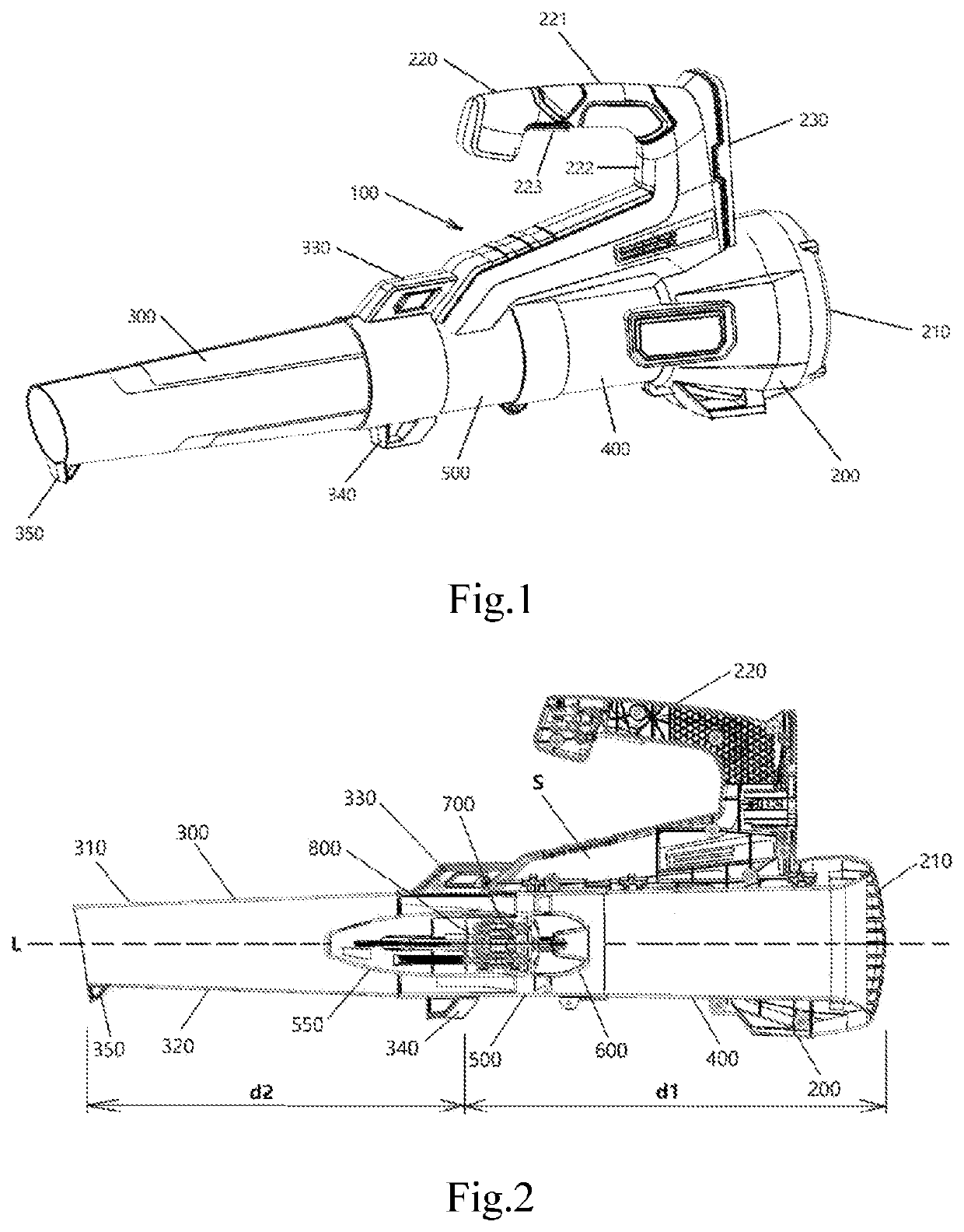
[0029]FIG. 1 shows a blower according to an embodiment of the present invention; the blower is an axial-flow blower, and comprises a blower body 100 and a blow pipe 300 mounted on the blower body 100. A fan, and a drive unit driving the fan to rotate, are accommodated in the blower body 100. In a state of not being used, a user can remove the blow pipe 300 from the blower body 100 to reduce storage space. The blower defines an airflow path from an air inlet to an air outlet. The air inlet is formed on the blower body 100, while the air outlet is formed on the blow pipe 300. To facilitate description, in this text, a straight line on which a rotation shaft of the fan in the blower lies is defined as a longitudinal axis, a side facing toward the air outlet is called a far side, and a side facing toward the air inlet is called a near side. In this embodiment, the blow pipe 300 is connected to the blower body 100 via a snap-fit connector 330 located at the near side thereof. It should b...


PUM


Abstract

A blower, comprising: a blower body, having accommodated therein a fan and a drive unit, a rotation shaft of the fan defining a longitudinal axis, and the blower body defining an air inlet; a blow pipe, attached to the blower body and extending along the longitudinal axis, the blow pipe defining an air outlet; and a control unit, for controlling operation of the drive unit. The blower defines an airflow path extending from the air inlet to the air outlet, the control unit being at least partially located in the airflow path, such that when the blower is operating, at least a portion of an airflow entering the air inlet cools the control unit and is then discharged through the air outlet.

Description

TECHNICAL FIELD[0001]The present invention relates to a blower, in particular to a blower for gardening work.BACKGROUND ART[0002]Leaf blowers are mainly used for blowing away fallen leaves, road surface dust, accumulated water and accumulated snow, etc. Common types of blower include petrol blowers and electric blowers. During operation, a petrol blower is powered by a petrol engine; fan blades rotate inside a fan volute, producing a wind which blows out through an air outlet to perform a job. In contrast to a petrol blower, an electric blower in which the fan is driven to rotate by a motor is small in volume, light in weight and convenient to operate, and is therefore popular among consumers.[0003]When an electric blower is operating, electronic components on a circuit board for controlling the motor generate heat, causing a rapid increase in the temperature of the circuit board and its surroundings. The electronic components will fail due to overheating if this heat is not promptl...

Claims


Application Information

Patent Timeline
IPC IPC(8): F04D25/06F04D29/40F04D29/58
CPCF04D25/06F04D29/403A01G20/47F04D29/582F04D29/5813F04D25/08F04D27/00F04D29/002F04D29/522F04D29/545F04D29/5806H05K7/20145
Inventor LEE, HEI MAN
Owner TECHTRONIC CORDLESS GP
Why Eureka
Try Eureka