[0034]Elements or parts in common to the embodiments described will be indicated hereafter using the same reference numerals.
DETAILED DESCRIPTION
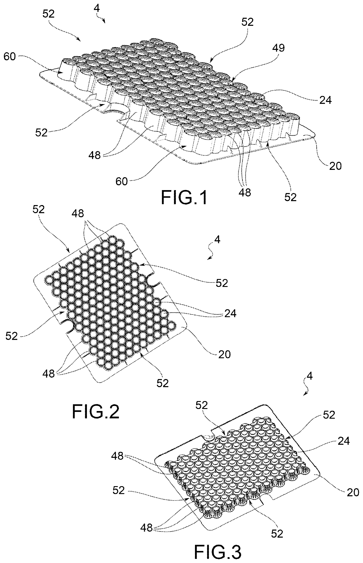
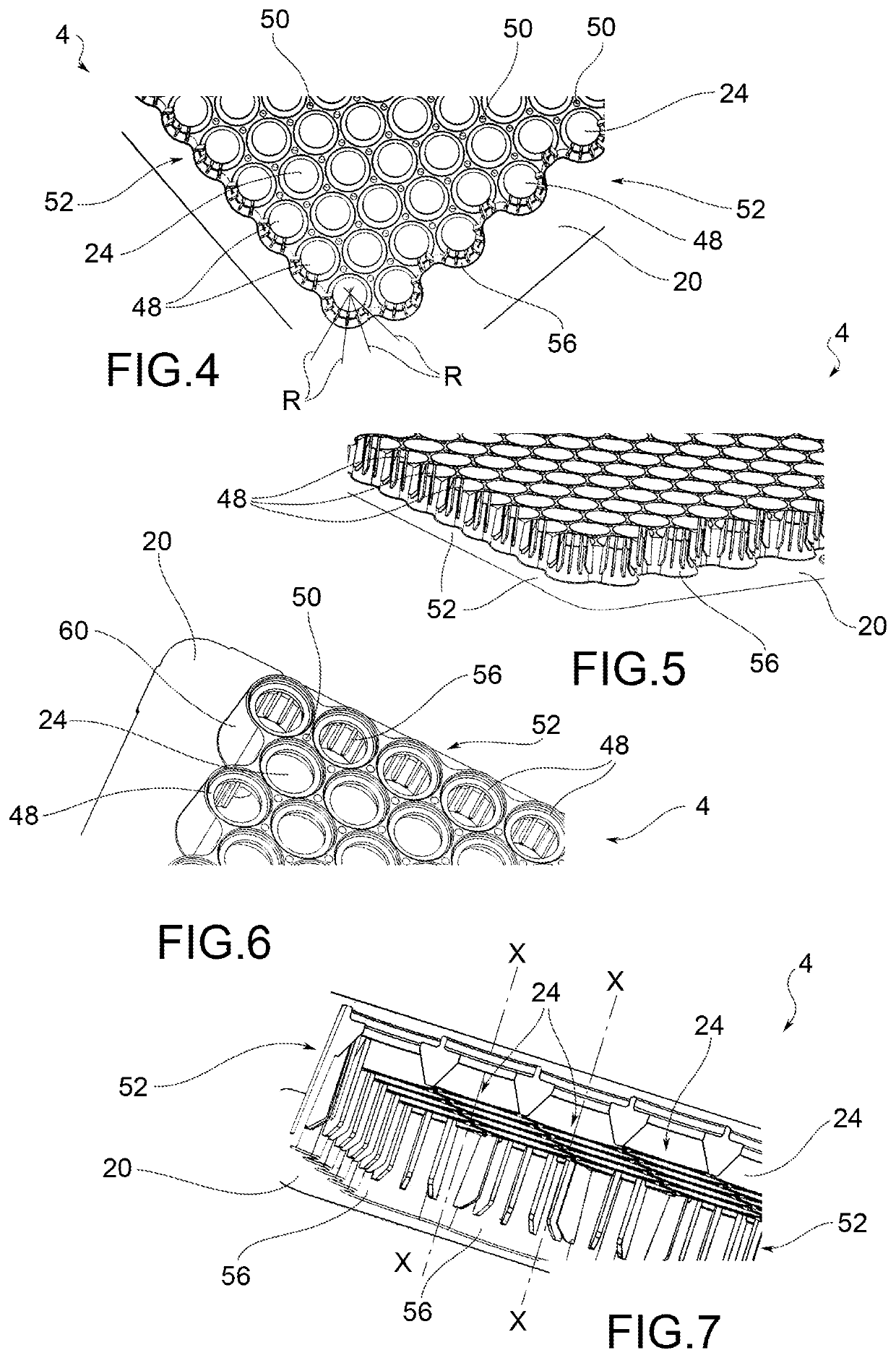
[0035]With reference to the aforementioned figures, reference numeral 4 indicates an overall view of a structure for packaging containers 8 for pharmaceutical use.
[0036]It is worth noting that, for the purposes the scope of protection of the present invention, the specific type of containers for pharmaceutical use is not relevant, meaning containers of various types, sizes and/or materials, such as syringes, vials, tubular injection vials, bottles and the like or medical devices with or without means of containing a pharmaceutical, such as autoinjectors with or without Carpule or the like.
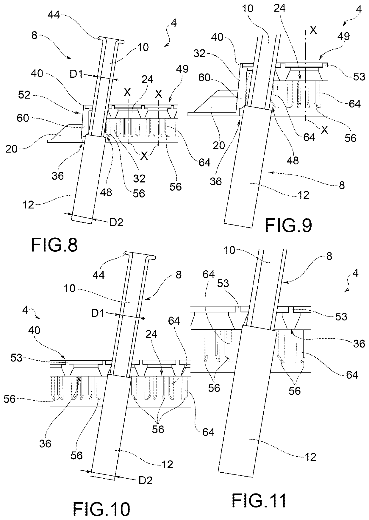
[0037]In particular, as shown in greater detail below, the present invention is advantageously applied when containers 8 having a double diameter, i.e. a first portion or upper portion 10 having a first diameter D1 and a second portion or lower portion 12 having a second diameter D2, preferably larger than said diameter D1, are used.
[0038]The structure 4 comprises a tray 16 which houses and supports a support plane 20 provided with a plurality of seats 24 for housing said containers 8 for pharmaceutical use.
[0039]Furthermore, the tray 16 has a bottom 28, which is preferably closed.
[0040]The seats 24 have main extension axes X-X, parallel to each other.
[0041]Typically, the seats 24 have a cylindrical shape with respect to main extension axes X-X, parallel to one another. Such main extension axes are preferably perpendicular to the support plane 20.
[0042]The seats 24 being delimited by side walls 32 which extend from a lower end 36 to an upper end 40, wherein said upper end 40 is facing and configured to receive in abutment a collar or neck 44 of an associable container 8 for pharmaceutical use.
[0043]The side walls 32 of the seats 24,48 have cylindrical circular cross-section with respect to a section plane perpendicular to said main extension axes X-X.
[0044]Furthermore, the side walls 32 of mutually adjacent seats 24,48 are mutually tangent, thus identifying a plurality of through holes 50.
[0045]According to an embodiment, on the side of an upper face 49 of the seats 24,48, intended to receive in abutment the collar 44 of said containers 8 for pharmaceutical use, there is a raised perimeter 53 of each seat 24,48 adapted to delimit and surround at least partially an annular pocket, enlarged with respect to the seat 24,48 and destined to receive in abutment said collar 44.
[0046]Advantageously, the perimeter seats 48, arranged externally along a perimeter edge 52 of the support plane 20, have, at said lower end 36, at least one guide or chamfer 56 diverging as it moves away from the lower end 36, opposite to the upper end 40.
[0047]According to an embodiment, the side walls 32 of said perimeter seats 48 have a stepped portion 60, connecting to said support plane 20, to create a spacer between the support plane 20 and the upper end 40 of the side walls themselves; preferably, said guide or chamfer 56 is arranged at said stepped portion 60.
[0048]The spacer has the further function of stiffening the structure 4 so that it does not inflect under its own weight and the weight of the containers 8 housed in the respective seats 24.
[0049]The guide or chamfer 56 is at least partially counter-shaped with respect to the side wall from which it protrudes to direct the container symmetrically towards the centre of the corresponding perimeter seat 48, during both the step of inserting and during the step of extracting.
[0050]The guide or chamfer 56 can be made in various geometries or shapes.
[0051]According to a possible embodiment, said chamfer 56 is made by means of a continuous shelf projecting from the side wall 32, preferably with respect to each corresponding stepped portion 60.
[0052]According to a further embodiment, said chamfer 56 is made by means of a plurality of fins 64, separated or spaced from each other.
[0053]Preferably, said fins 64 are arranged in radial R-R directions with respect to the corresponding perimeter seats 48.
[0054]According to an embodiment, the side walls 32 of adjacent perimeter seats 48 are at least partially interlocking with one another; this further increases the structural rigidity of the containment structure 4. For example, such an interlocking and/or connection may be achieved by means of brackets or connection rods 68.
[0055]According to a possible embodiment, said guide or chamfer 56 has a truncated conical section, with respect to a section plane perpendicular to the support plane 12.
[0056]For example, the truncated conical section has a taper angle, with respect to a perpendicular to support plane 12, between 30 and 60 degrees.
[0057]Said taper angle can be between 40 and 50 degrees and is preferably 45 degrees.
[0058]According to a possible embodiment, said guide or chamfer 56 has a parabolic arc cross-section, with respect to a section plane perpendicular to the support plane 12.
[0059]In turn, the side walls 32 of the seats 24,48 have a converging taper from the lower end 36 towards the upper end 40.
[0060]Preferably, said taper is either greater than or equal to the taper of said guide or chamfer 56.
[0061]The best guide of the containers 8 for pharmaceutical use during the entire step of extracting from the perimeter seats 48 is achieved in this manner.
[0062]According to a possible embodiment, said guide or chamfer 56 is aligned with a through opening of the corresponding perimeter seats 48, at the upper end 40, with respect to a vertical direction, perpendicular to said support plane 20 and parallel to said main extension axes X-X.
[0063]As can be appreciated from the description above, the present invention allows to overcome the drawbacks presented in the prior art.
[0064]First, by virtue of the presence of the perimeter chamfers, there is no risk of sticking during the moving/lifting of the primary containers: indeed, the chamfers accompany the “sliding” of the undercut at the lower wall of the nest ensuring the correct passage of the undercut.
[0065]This condition is illustrated in FIGS. 8-11 in which it is shown how the chamfers tend to align the containers without the respective portions passing from the lower portion, with a larger diameter, to the upper portion, with a smaller diameter, being stuck or sticking at the lower portions of the perimeter seats during the step of lifting the containers themselves.
[0066]Furthermore, the chamfers create a real guide which ensures a given perpendicularity of the containers with respect to the nest; the risk of accidental contact between adjacent primary containers is avoided in this manner.
[0067]Furthermore, the structure has sufficient mechanical stiffness and/or geometric conformation to ensure a reduced elastic deflection of the structure under its own weight and that of the containers it supports, with particular reference to the condition in which the latter are filled.
[0068]In this manner, it is always ensured that the containers are correctly aligned within their respective seats, even under conditions of maximum loading of the structure and its containers, e.g. in the case of containers filled with the medicine.
[0069]Furthermore, any risk of contact between the collars of nearby containers is prevented, because the collars are contained in pockets or seats delimited by the raised perimeter.
[0070]Therefore, said raised perimeters, e.g. in the form of pins or protuberances, prevent any kind of contact between the collars of neighbouring containers.
[0071]The parallelism between the containers, with respect to a vertical direction, is ensured not only by the high structural rigidity of the containment structure but also by the fact that the collars rest in abutment on a flat edge with a circular crown shape, being said edge perpendicular to said vertical direction.
[0072]Furthermore, the presence of the raised perimeter also ensures the correct radial distance between the containers and, therefore, allow the grippers of a manipulator to be inserted without impact into the gaps between adjacent containers. Such a correct radial distance further helps to avoid the risk of accidental collisions between neighbouring containers.
[0073]In order to meet contingent, specific needs, those skilled in the art can make several changes and variations to the structures described above, all contained within the scope of the invention as defined by the following claims.