Ophthalmic solution container

a container and solution technology, applied in the field of self-standing containers, can solve the problems of low fluidity poor loading efficiency of containers filled with contents, and difficulty in use, and achieve the effect of strength and disposability

Pending Publication Date: 2022-08-18
FUJIMORI KOGYO CO LTD
View PDF3 Cites 0 Cited by
  • Summary
  • Abstract
  • Description
  • Claims
  • Application Information

AI Technical Summary

Benefits of technology

[0015]According to the present invention, since an annular member is bonded between a flexible tubular member and a lid member and a container is constituted to open and close between the lid member and the annular member, it is possible to achieve both strength and disposability even if the container has a wide mouth.

Problems solved by technology

However, utilization of such a container, in particular for contents having low fluidity such as creams and solids, has been difficult.
Also, although flexible packaging containers mainly formed of laminated films are lightweight and have excellent disposability, the loading efficiency of the containers filled with the contents is poor and the container strength such as drop strength or bag breaking strength is low.
Furthermore, although containers such as paper cartons and brick pack (registered trademark) which are often seen today have a stable shape and excellent loading efficiency and are lightweight, since the strength of the container, particularly the interlayer strength of a base material used for a paper container is inferior, there is a problem that the container is vulnerable to impacts such as dropping, depending on the shape of the container.
In addition, paper containers are inferior in piercing resistance and the appearance design such as the gloss may be inferior to that of film containers.
Meanwhile, molded containers such as blow bottles, aluminum cans, and the like have high strength, but are bulky when discarded.

Method used


Image

  • Ophthalmic solution container
  • Ophthalmic solution container
  • Ophthalmic solution container

Examples


Embodiment Construction

[0030]The present invention will be described below with reference to the drawings on the basis of preferred embodiments.

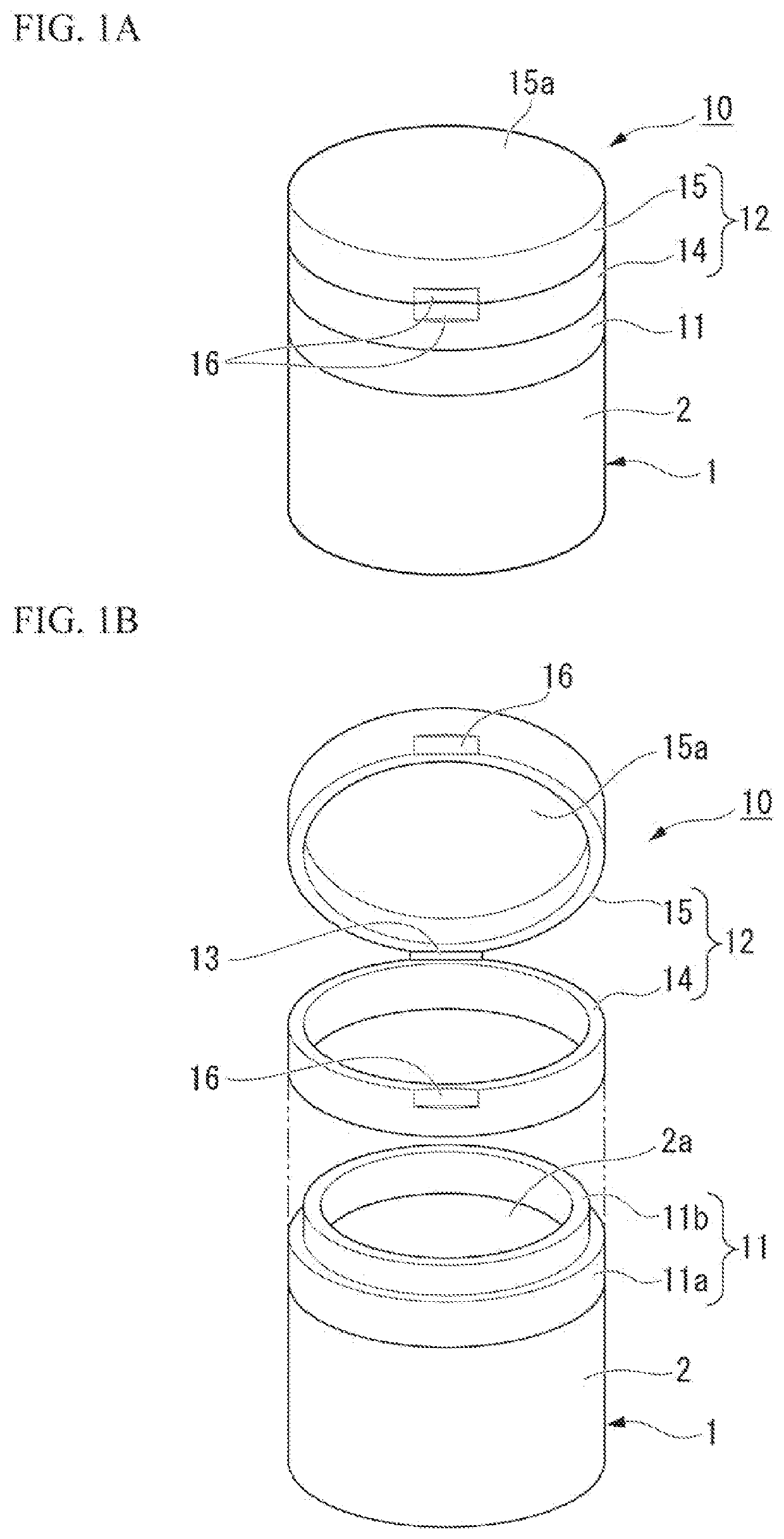
[0031]FIGS. 1A and 1B show a container 10 according to a first embodiment. The container 10 includes a container body 1 having an opening part 2a at an upper end of a tubular member 2, an annular member 11 that is bonded to the upper end of the tubular member 2, and a lid member 12 that seals the opening part 2a to be openable and closable. The lid member 12 has a base part 14 that can be bonded to the annular member 11 and a top part 15 that is coupled to the base part 14 via a hinge 13 to be openable and closable. The base part 14 has a ring shape and the top part 15 has a closed top surface part 15a. When sealing the contents is not required, a hole may be provided in the top surface part 15a or a mesh, a grid, or the like may be provided thereon.

[0032]In the first embodiment, the top part 15 may be constituted to be coupled to the annular member 11 via the hin...


PUM

PropertyMeasurementUnit
outer diameteraaaaaaaaaa
thicknessaaaaaaaaaa
thicknessaaaaaaaaaa

Abstract

A self-standing packaging container capable of achieving both strength and disposability even if the container has a wide mouth is provided. A container according to the present invention includes: a container body that has an opening part at an upper end of a tubular member; an annular member that is bonded to the upper end of the tubular member; and a lid member that seals the opening part to be openable and closable. The container body has a bottom surface member that is bonded to the tubular member at a bottom surface part of the tubular member. The tubular member is constituted by a flexible laminated body of three or more layers including a barrier layer and a resin layer. The lid member is coupled to the annular member by any of a hinge, fitting, and a screw to be openable and closable.

Description

CROSS-REFERENCE TO RELATED APPLICATIONS[0001]Priority is claimed on Japanese Patent Application No. 2019-123825, filed Jul. 2, 2019, the content of which is incorporated herein by reference.FIELD OF THE INVENTION[0002]The present invention relates to a self-standing container.BACKGROUND OF THE INVENTION[0003]Patent Literature 1 (Japanese Unexamined Patent Application, First Publication No. 2015-20787) describes a pouch container obtained by forming annular body side end joints bent inward at upper and lower ends of a body member, respectively, bonding outer circumferential parts of upper and lower closing members to the upper and lower body side end joint, respectively, and closing the upper and lower ends of the body member with the upper and lower closing members.SUMMARY OF THE INVENTIONProblems to be Solved[0004]The pouch container described in Patent Literature 1 can have excellent self-standing stability and shape retention, excellent design, volume reduction, and sufficiently-...

Claims


Application Information

Patent Timeline
Patent Type & Authority Applications(United States)
IPC IPC(8): B65D43/16B65D1/10B65D43/02
CPCB65D43/169B65D1/10B65D2543/00527B65D2543/00092B65D2543/00537B65D43/0231B65D11/16B65D43/22B65D15/16B65D75/008B65D43/163B65D2251/023B65D75/5872B65D43/08B65D43/0225B65D43/0204B65D43/162
Inventor YOSHIDA, MIHOKOSUZUKI, TOYOAKI
Owner FUJIMORI KOGYO CO LTD
Why Eureka
Try Eureka