Unlock instant, AI-driven research and patent intelligence for your innovation.

Self cleaning filtering apparatus for plate heat exchangers

a filtering apparatus and heat exchanger technology, applied in the direction of flush cleaning, lighting and heating apparatus, laminated elements, etc., can solve the problems of heat exchanger inevitable, heat exchanger efficiency, and severe reduction of heat exchange efficiency

Pending Publication Date: 2022-08-25
LIVNI ZVI +1
View PDF7 Cites 2 Cited by
  • Summary
  • Abstract
  • Description
  • Claims
  • Application Information

AI Technical Summary

Benefits of technology

The present invention provides a self-cleaning filtering apparatus for a plate heat exchanger that includes a suction pipe, nozzles, a low pressure chamber, a drain valve, and a rotation mechanism controlling axial rotation of the suction pipe. The apparatus can effectively filter particulate matter from the cooling medium and create a negative pressure on the suction pipe to remove any particles. The apparatus can be manually or automatedly operated, and a linear actuator can be used to move the suction pipe and nozzles. The invention also includes a screen cylinder for filtering particulate matter from the cooling medium. The technical effects of the invention include improved cooling efficiency, reduced maintenance costs, and improved operational reliability.

Problems solved by technology

Impurities such as rust, debris, biofilm and other various types of suspended solids present in the water penetrate the heat exchanger and block the water conduits reducing the efficiency of a heat exchanger to the extent that its heat exchange efficiency is severely reduced, which makes cleaning of the heat exchanger inevitable.
Cleaning plate heat exchangers is a long and cumbersome operation that usually requires the heat exchange process to be stopped, and the heat exchanger to be opened, wasting a considerable amount of time and causing a loss of production, This process is not done on a daily basis and is avoided as much as possible.
Therefore, the accumulation of the suspended matter in the heat exchangers causes significant efficiency loss between cleanups.

Method used


Image

  • Self cleaning filtering apparatus for plate heat exchangers
  • Self cleaning filtering apparatus for plate heat exchangers
  • Self cleaning filtering apparatus for plate heat exchangers

Examples


Embodiment Construction

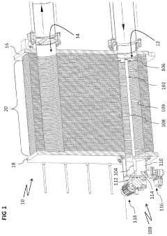
[0024]Plate heat exchangers have various configurations and different people use slightly different terminology for the various parts of the plate heat exchanger. In order to minimize confusion and present a clear nomenclature for the various components of the plate heat exchanger, the following description is provided.

[0025]The instant innovative apparatus is disclosed with reference to a specific configuration of plate heat exchangers. However, it is made clear that the use of the instant configuration of heat plate exchanger is merely exemplary, and in no way limiting of the scope of the invention. The instantly described apparatus can be implemented in any plate heat exchanger, with minor modifications where necessary.

[0026]At least for the purposes of the instant disclosure, the following terminology and configuration of the plate heat exchanger is used: A plate heat exchanger is made up of a frame plate, a pressure plate and a plate pack which is disposed between the frame pla...


PUM


Abstract

A self cleaning filtering method and apparatus for a plate heat exchanger including: a suction pipe, centrally disposed within an inlet channel adapted for receiving a cooling medium therein for the plate heat exchanger; nozzles extending radially from, and in fluid communication with, the suction pipe, the nozzles spaced apart from each other; a low pressure chamber, external to the heat exchanger, abutting the pressure plate, the low pressure chamber in fluid communication with the inlet channel, and a section of the suction pipe extending into the low pressure chamber; a drain valve adapted to reversibly open a drain of the low pressure chamber; and a rotation mechanism controlling axial rotation of the suction pipe.

Description

FIELD OF THE INVENTION[0001]The present invention is directed to a filtering apparatus for industrial and commercial plate heat exchangers.BACKGROUND OF THE INVENTION[0002]The process heat generated in plants and the like is dissipated with plate and tube heat exchangers. Plate heat exchangers have a multitude of very thin plates between which liquids or gas circulate, to enable heat exchange. Impurities such as rust, debris, biofilm and other various types of suspended solids present in the water penetrate the heat exchanger and block the water conduits reducing the efficiency of a heat exchanger to the extent that its heat exchange efficiency is severely reduced, which makes cleaning of the heat exchanger inevitable. Cleaning plate heat exchangers is a long and cumbersome operation that usually requires the heat exchange process to be stopped, and the heat exchanger to be opened, wasting a considerable amount of time and causing a loss of production, This process is not done on a ...

Claims


Application Information

Patent Timeline
IPC IPC(8): F28G9/00F28F19/01
CPCF28G9/00F28F19/01F28D9/005F28F3/083F28F9/0273F28F2265/06F28G15/003F28F2280/06
Inventor LIVNI, ZVILIVNI, OMER
Owner LIVNI ZVI