Check patentability & draft patents in minutes with Patsnap Eureka AI!

Overload protection switch with reverse restart switching structure

a technology of reverse restarting and overload protection switch, which is applied in the direction of protective switch details, protective switch operating/release mechanisms, relays, etc., can solve the problems of power supply tripping, power supply isolation, overload protection function loss, etc., and achieve the effect of preventing the danger of repeated tripping during overload

Active Publication Date: 2022-09-08
WANG YI HSIANG +1
View PDF7 Cites 0 Cited by
  • Summary
  • Abstract
  • Description
  • Claims
  • Application Information

AI Technical Summary

Benefits of technology

The present invention provides an overload protection switch with reverse restart switching structure that achieves making small overcurrent protection switch has multiple step fool-proof design like MCCB had and design with an unobstructed complete separation and tripping structure. The switch has a first brake plate of the moving rod and a third brake plate formed at the curve of the lower section of the moving rod, and an outwardly deviated moving rod that achieves three step fool-proof feature. The switch also has a lampshade parallel stagnation position for overload indication and a binary alloy conductive plate reorder in the correct order and then press the SET (on end) to restart. The reverse restart structure (fool proof) prevents repeated tripping during overload and the lampshade can be completely tripped even when the lampshade is suppressed, preventing the danger of repeated tripping during overload.

Problems solved by technology

When an overload or short circuit accident occurs, it will trip and isolate the power supply.
However, above mentioned conventional overcurrent protection switch 10 does not have the multiple step fool-proof design that molded-case circuit breaker has, due to the use of a cyclic tripping structure, when the lampshade 12 is pressed or stuck, the bimetal plate 13 is repeatedly connected and disconnected (ON↔OFF), repeated overloads resulting in loss of overload protection function, so the service life and use safety need to be improved.

Method used


Image

  • Overload protection switch with reverse restart switching structure
  • Overload protection switch with reverse restart switching structure
  • Overload protection switch with reverse restart switching structure

Examples


Embodiment Construction

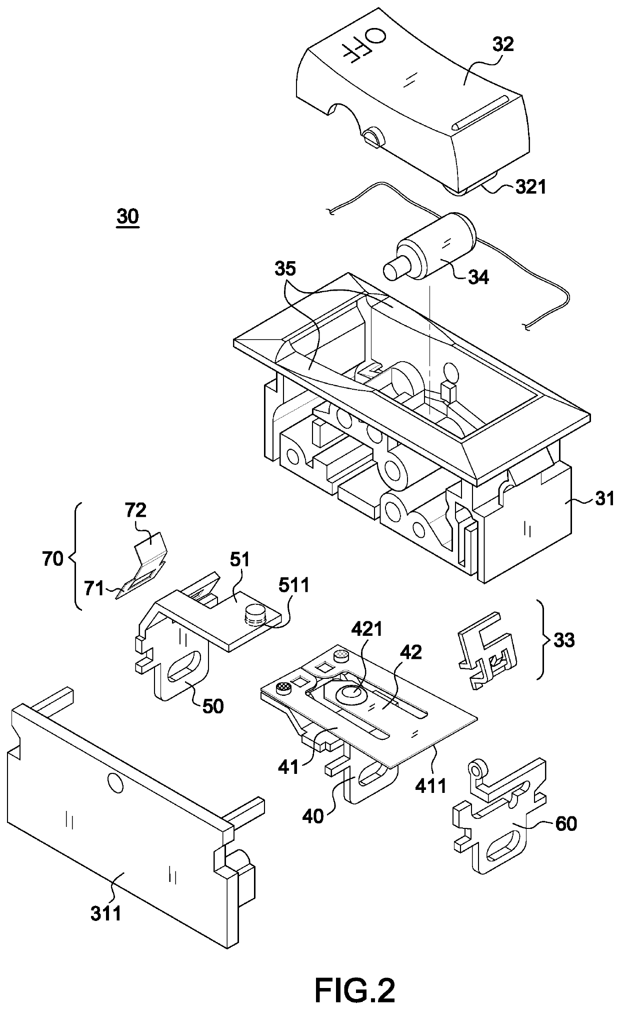
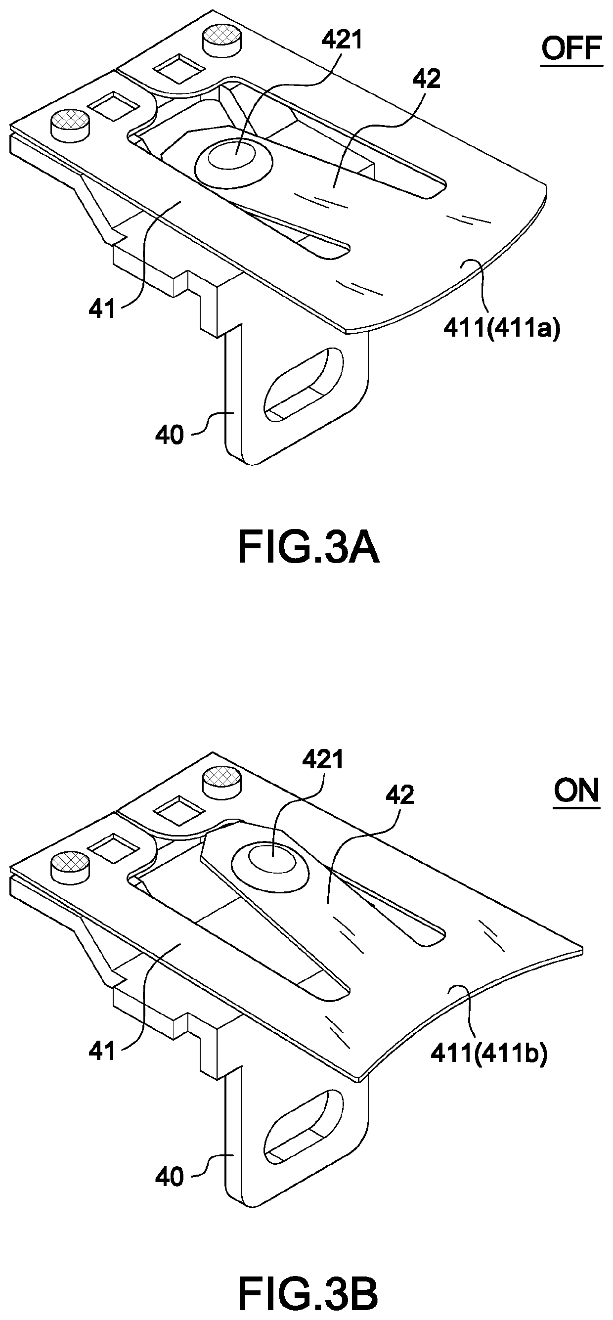
[0031]Referring to FIGS. 2-8B, the circuit breaker 30 of the present invention in preferred embodiment includes a housing 31 having a lampshade 32 arranged atop thereof, below the lampshade 32 further includes a neon lamp 34, and a first terminal 40 and a second terminal 50 arranged at the bottom section, in this embodiment further having a third terminal 60, but not limited to such application. The first terminal 40 is connected to a binary alloy conductive plate 41, the inner side of the movable end 411 of the binary alloy conductive plate 41 extends a spring leaf 42 the movable end 411, above the movable end 411 having a first connecting point 421, and the second terminal 50 having a second connecting point 511 on the surface of an upper section 51 thereof corresponding to the first connecting point 421; in this embodiment, the housing 31 further includes a side cover 311.

[0032]FIG. 3A is a perspective view showing the movable end 411 of the binary alloy conductive plate 41 which...


PUM


Abstract

An overload protection switch with reverse restart switching structure, particularly to one that has a molded-case circuit breaker which adding a lampshade parallel stagnation position for overload indication, and when resetting, needs to press back to the RESET for reconfirmation; due to the stagnation position and reverse restart structure, it can avoid repeating the reset action, preventing the reduction of the life of the overload protection switch and repeated exposure or the misjudgment and then resetting of electrical products that have been overloaded and tripped and then overload again then results in causing dangerous; also, the lampshade can be completely tripped even when the lampshade is suppressed, and prevent the danger of repeated tripping during overload.

Description

BACKGROUND OF THE INVENTION1. Field of the Invention[0001]The present invention relates to an overload protection switch with reverse restart switching structure, particularly to one that has an overload protection and three step fool-proof design molded-case circuit breaker.2. Description of the Related Art[0002]Low-voltage circuit breaker, Europe and America call molded-case circuit breaker (MCCB) is a low-voltage over-current protection circuit breaker. Compared with miniature circuit breaker (MCB), molded-case circuit breaker has a larger rated current and breaking capacity, in Taiwan and Japan is called non-fuse circuit breaker (NFB), another product with leakage protection is classified as electricity leakage circuit breaker (ELCB), and for products with relatively small capacity, it is called MCB Or ELB. Usually, MCCB and ELCB circuit breakers are used for large breaking capacity, commonly known as industrial type. MCB and ELB are used for small interruption capacity, commonl...

Claims


Application Information

Patent Timeline
Patent Type & Authority Applications(United States)
IPC IPC(8): H01H73/14H01H47/00H01H21/20H01H71/50
CPCH01H73/14H01H47/002H01H21/20H01H71/504H01H71/54H01H73/26
Inventor WANG, YI-HSIANGWANG, I-YING
Owner WANG YI HSIANG
Features
  • R&D
  • Intellectual Property
  • Life Sciences
  • Materials
  • Tech Scout
  • Unparalleled Data Quality
  • Higher Quality Content
  • 60% Fewer Hallucinations
Learn More