

Apparatus and method for manufacturing absorbent body
a technology of absorbent body and absorbent material, which is applied in the direction of absorbent pads, undergarments, apparel, etc., can solve the problems of inability to obtain the intended sap spraying pattern, difficult to arrange the sap in the absorbent body, and mixed fibers and sap conveyed via air flow
- Summary
- Abstract
- Description
- Claims
- Application Information
AI Technical Summary
Benefits of technology
Problems solved by technology
Method used
Image

Examples
embodiment 1
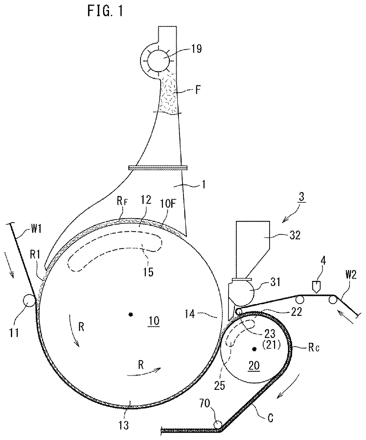
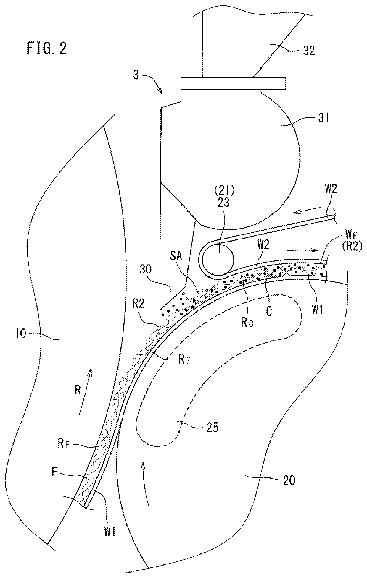
[0050]The following section will describe the respective embodiments of the present invention. FIG. 1 to FIG. 3 illustrate
[0051]Prior to the description of the manufacturing apparatus, the following section will describe one example of the absorbent body generated by the manufacturing apparatus.
[0052]The absorbent body manufactured by the manufacturing apparatus is also called an absorbent core. The absorbent body is used as a core of disposable shorts or a diaper for example or as a core of an incontinence pad for example and has a sandglass-like shape, for example.
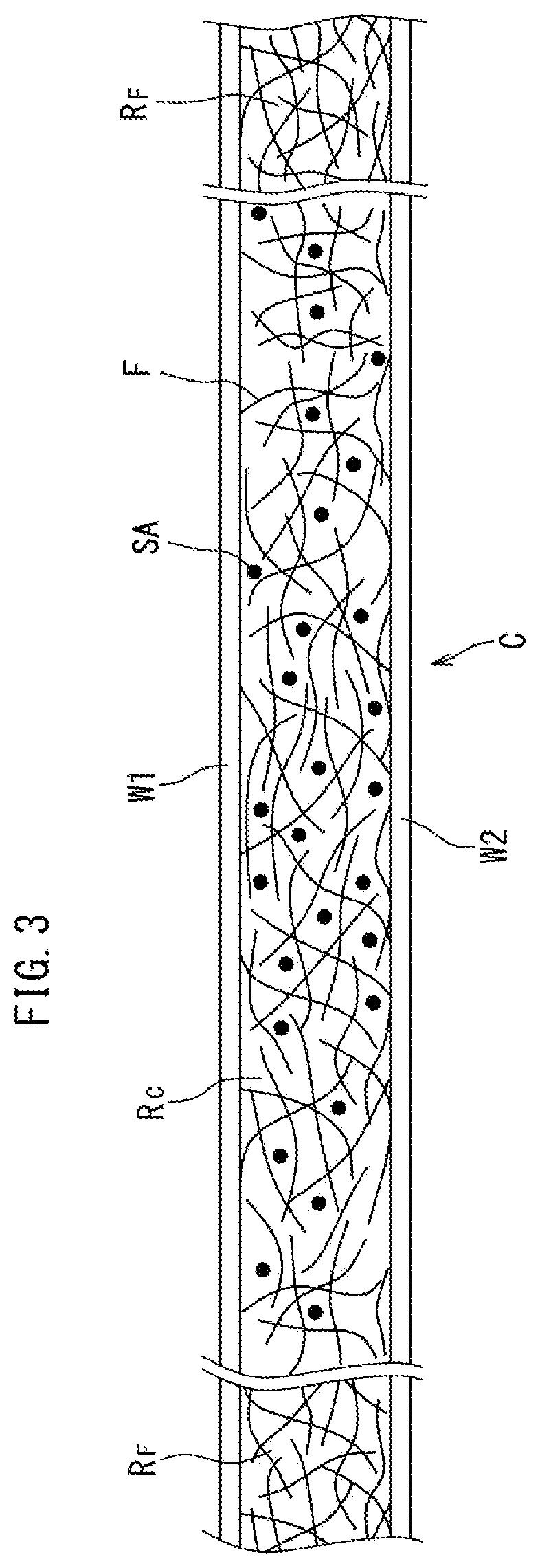
[0053]As shown in FIG. 3, the absorbent body C includes the absorber layer RC as well as the first and second carrier webs W1 and W2. The respective webs W1 and W2 may be a thin paper such as a tissue paper or may be a non-woven fabric.
[0054]The respective webs W1 and W2 may be arranged to sandwich the absorber layer RC and may cover the absorber layer RC. The respective webs W1 and W2 have high diffusibility in a plane ...
embodiment 4
[0091]FIG. 7 to FIG. 10 illustrate Embodiment 4 of the manufacturing apparatus.
[0092]Prior to the description of the manufacturing apparatus of this embodiment, the following section will describe another example (FIG. 6) of the absorbent body manufactured by the manufacturing apparatus.
[0093]The absorbent body manufactured by the manufacturing apparatus is used as a core of disposable shorts and diaper as well as an incontinence pad for example and has a sandglass-like shape for example.
[0094]As shown in FIG. 6(d), the absorbent body C includes the absorber layer RC as well as the first and second carrier webs W1 and W2. The respective webs W1 and W2 may be a thin paper such as tissue paper or may be a non-woven fabric.
[0095]The respective webs W1 and W2 are provided so as to sandwich the absorber layer RC and may surround the absorber layer RC. The respective webs W1 and W2 have high diffusibility in the plane direction and thus allows liquid to penetrate in a wide range.
[0096]The...
embodiment 5
[0138]FIG. 11 illustrates Embodiment 5 of the manufacturing apparatus.
[0139]As shown in this drawing, the generated absorbent body C may be outputted to the side at which the first carrier web W1 is introduced (the first introduction device 11 side). It is noted that, in Embodiment 4 of FIG. 7, the generated absorbent body C is outputted to the side at which the second carrier web W2 is introduced (the second introduction device 21 side). By selecting one of the layouts of FIG. 7 and FIG. 11, an arrangement appropriate for the wearable article manufacture line can be selected.
[0140]The other details for the structure and the method for manufacturing the absorbent body are similar to those of Embodiment 4 and thus will not be further described.
[0141]The respective embodiments described above mainly include the invention having a configuration described below.
[0142]In one of the above-described aspects, a preferred manufacturing apparatus further includes: the first introduction devic...
PUM
 Abstract
Description
Claims
Application Information