Count per inch calibration method and optical navigation device

a calibration method and optical navigation technology, applied in the direction of instruments, computing, electric digital data processing, etc., can solve the problems of complicated equipment, conventional cpi calibration methods do not provide a recommended cpi, and users may feel the optical mouse moves too fast, etc., to achieve the effect of simple steps

Active Publication Date: 2022-09-15
PIXART IMAGING INC
View PDF1 Cites 0 Cited by
  • Summary
  • Abstract
  • Description
  • Claims
  • Application Information

AI Technical Summary

Benefits of technology

[0010]In view of above-mentioned embodiments, the CPI of an

Problems solved by technology

If the CPI is too low, the user may feel the optical mouse does not move smoothly.
On the opposite, if the CPI is too high, the user may feel t

Method used


Image

  • Count per inch calibration method and optical navigation device
  • Count per inch calibration method and optical navigation device
  • Count per inch calibration method and optical navigation device

Examples


Embodiment Construction

[0018]Several embodiments are provided in following descriptions to explain the concept of the present invention. Each component in following descriptions can be implemented by hardware (e.g. a device or a circuit) or hardware with software (e.g. a program installed to a processor). Besides, the method in following descriptions can be executed by programs stored in a non-transitory computer readable recording medium such as a hard disk, an optical disc or a memory. Additionally, the term “first”, “second”, “third” in following descriptions are only for the purpose of distinguishing different one elements, and do not mean the sequence of the elements. For example, a first device and a second device only mean these devices can have the same structure but are different devices.

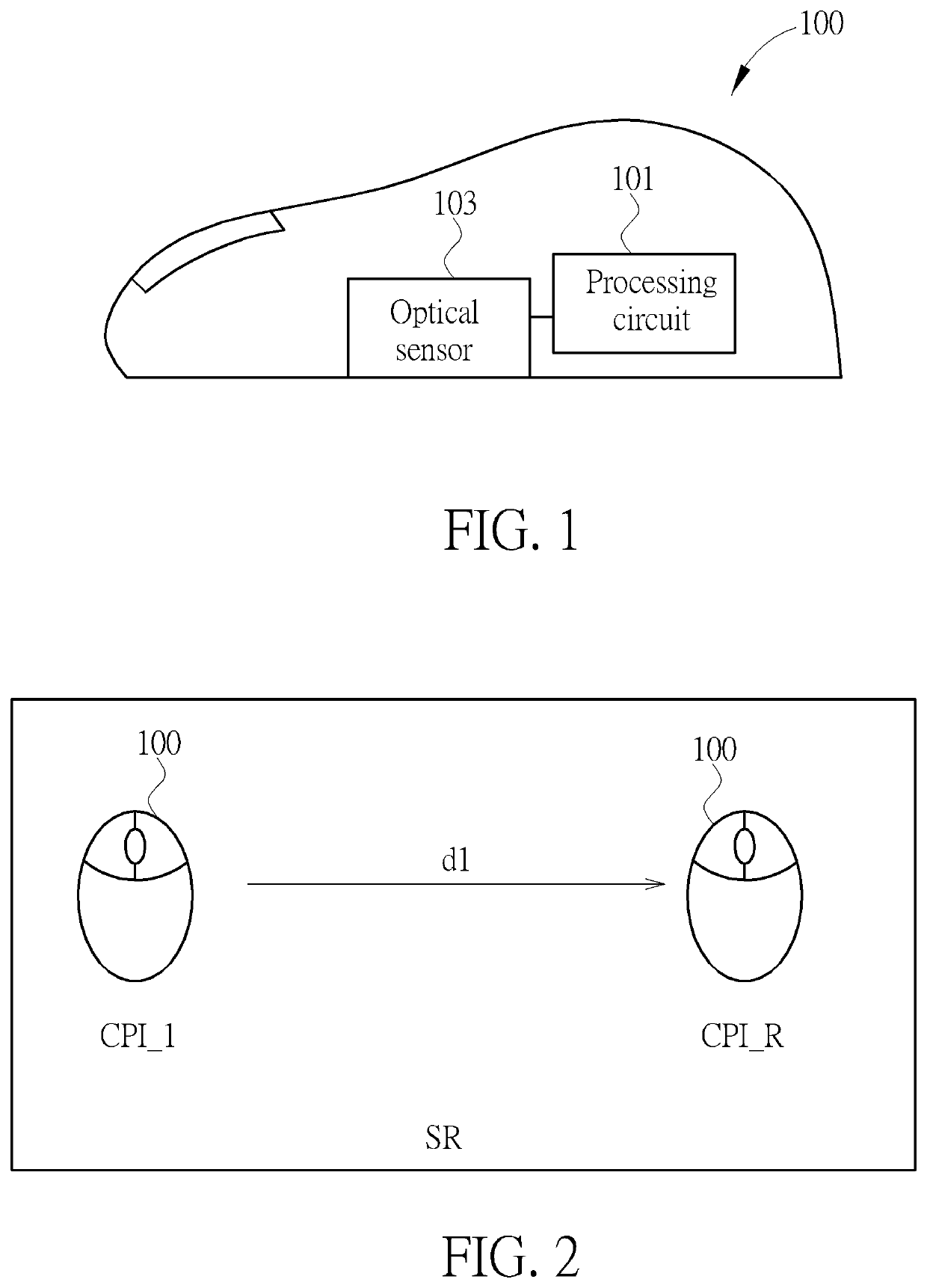
[0019]FIG. 1 is a schematic diagram illustrating an optical mouse 100 according to one embodiment of the present invention. Please note, in following embodiments, an optical mouse is used as an example for explai...


PUM


Abstract

An optical navigation device, comprising: an optical sensor, configured to sense optical data; and a processing circuit, configured to compute motions of the optical navigation device based on the optical data, and configured to output the motions, wherein a first CPI is set to the processing circuit. The processing circuit receives a calibration command to calibrate the first CPI to a second CPI, wherein the second CPI is computed via following steps: (a) computing a real CPI corresponding to times of motions output by the processing circuit during a time interval that a relative displacement between the optical navigation device and a surface reaches a first predetermined distance; (b) computing a ratio between the real CPI and the first CPI or a difference between the real CPI and the first CPI; and (c)generating the second CPI based on the ratio or the difference.

Description

CROSS REFERENCE TO RELATED APPLICATIONS[0001]This application claims the benefit of U.S. Provisional Application No. 63 / 160,937, filed on Mar. 15, 2021, the contents of which are incorporated herein by reference.BACKGROUND OF THE INVENTION1. Field of the Invention[0002]The present invention relates to a CPI (Counter Per Inch) calibration method and an optical navigation device, and particularly relates to a CPI calibration method and an optical navigation device which can calibrate CPI based on a calibration ruler pattern.2. Description of the Prior Art[0003]A CPI is an important parameter fora conventional optical mouse, since CPI means a frequency that the optical mouse outputs motions thereof to a host such as a computer. If the CPI is too low, the user may feel the optical mouse does not move smoothly. On the opposite, if the CPI is too high, the user may feel the optical mouse moves too fast. Therefore, it is necessary to set a proper CPI to the optical mouse.[0004]Due to the a...

Claims


Application Information

Patent Timeline
IPC IPC(8): G06F3/0354G06F3/038G06F3/03
CPCG06F3/03543G06F3/0383G06F3/0317G06F3/038G01C21/20G06F3/0321
Inventor LI, JR-YI
Owner PIXART IMAGING INC
Why Eureka
Try Eureka