Universal clamp apparatus for bone fixation device

a universal clamping and bone fixation technology, applied in the field of fractures and deformations, can solve the problems of low risk and the loss of stability of the universal clamping apparatus, and achieve the effect of extraordinary tightening precision

Active Publication Date: 2022-09-22
INFIX INC
View PDF6 Cites 0 Cited by
  • Summary
  • Abstract
  • Description
  • Claims
  • Application Information

AI Technical Summary

Benefits of technology

[0010]Embodiments of a new universal clamp apparatus for a multi-purpose orthopedic exterior fixator and methods associated therewith are disclosed. Advantageously, the universal clamp apparatus can be operated without the need for tools and with extraordinary tightening precision. Furthermore, there is low risk that the universal clamp apparatus will lose stability, i.e., its grasp on the pin(s) and / or rods, in the event that it hits or catches on an object.

Problems solved by technology

Furthermore, there is low risk that the universal clamp apparatus will lose stability, i.e., its grasp on the pin(s) and / or rods, in the event that it hits or catches on an object.

Method used


Image

  • Universal clamp apparatus for bone fixation device
  • Universal clamp apparatus for bone fixation device
  • Universal clamp apparatus for bone fixation device

Examples


second embodiment

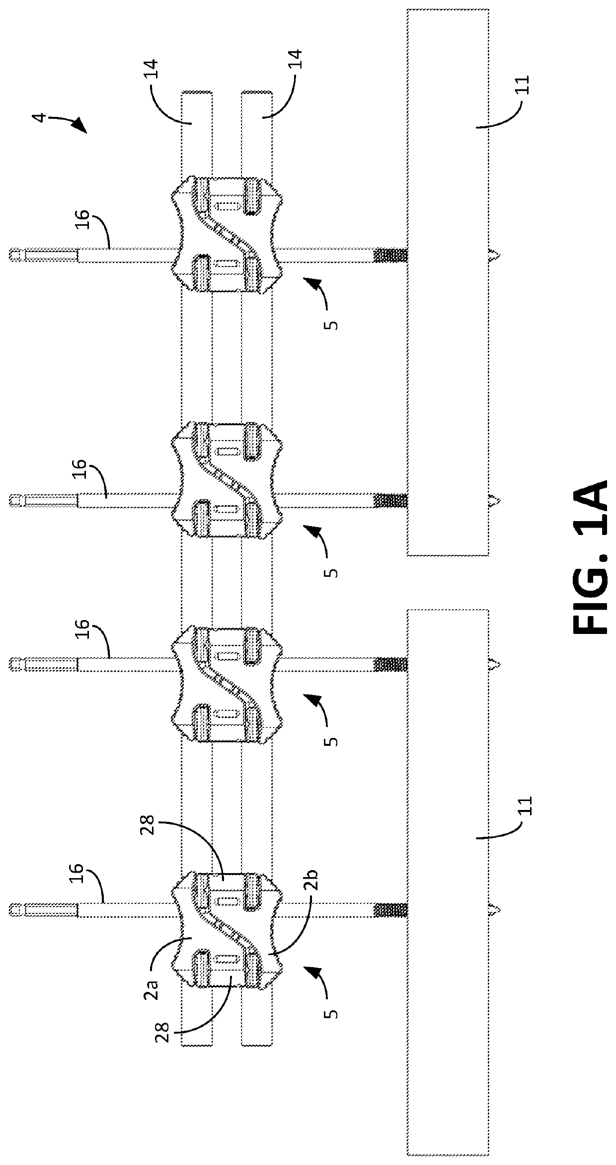
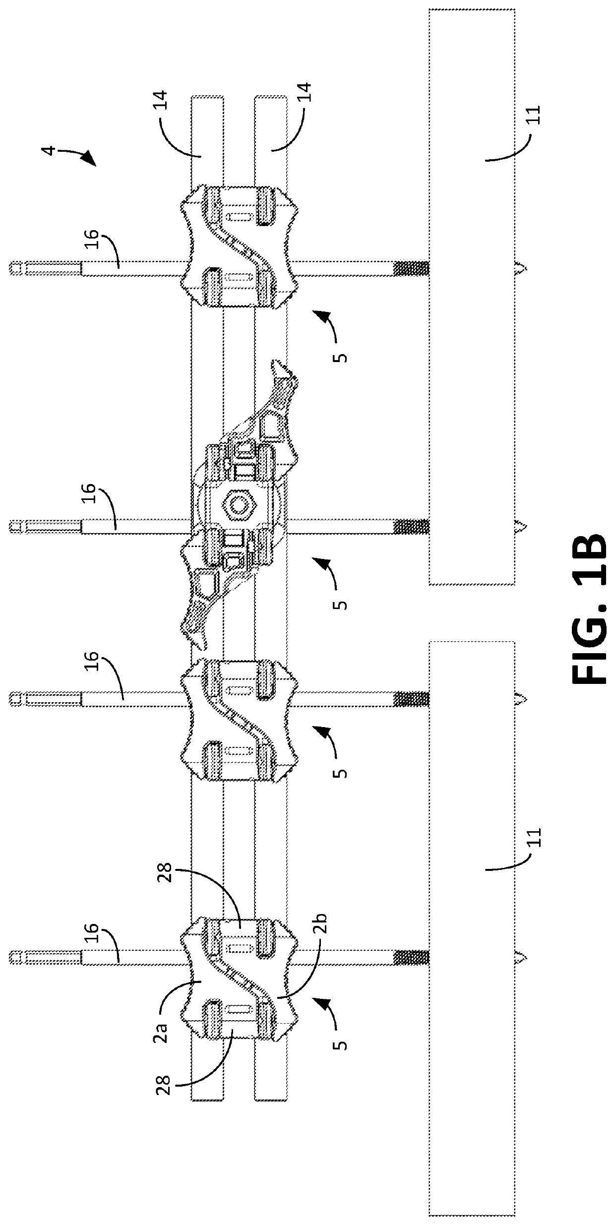
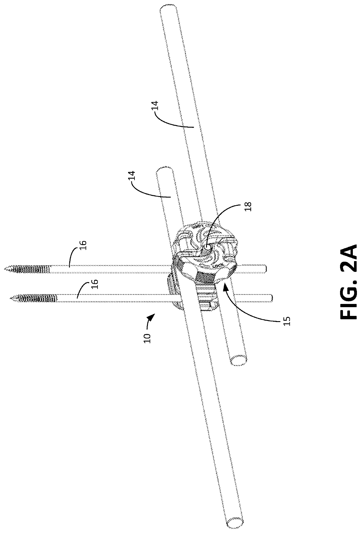
[0030]The universal clamp apparatus 10 has at least one but preferably two pin / rod clamps 12. In this second embodiment, there are first and second pin / rod clamps 12a, 12b. Each of the first and second pin / rod clamps 12a, 12b, has respective first and second attachment mechanisms (e.g., grooves) for attaching to at least two of the following: a frame rod 14 (e.g., 11 mm rod, 12 mm rod, etc.) associated with a frame of the fixator and / or at least one of a bone pin 16 for implantation in a bone 11. Each pin / rod clamp 12 should enable at least the following attachments: pin 16 to rod 14, rod 14 to rod 14, and pin 16 to pin 16. In this embodiment, there are two seating grooves 19 for rods 14 and two seating grooves 21 for bone pins 16 in each clamp 12a, 12b.

[0031]As shown in FIGS. 2A, 2B, and 2C, a frame rod(s) 14 can be situated in, or snapped in, a corresponding seating groove in the first clamp 12a and / or second clamp 12b, and a bone pin(s) 16 can also be situated in, or snapped in,...

third embodiment

[0039]More specifically, FIGS. 4A-4D show various views of the universal clamp apparatus and is generally denoted by reference numeral 40. Specifically, FIG. 4A is a perspective view of the universal clamp apparatus 40 with an ergonomic torque amplifying knob 41 having collapsible turn levers 42a, 42b in a closed position. FIG. 4B is a perspective view of the universal clamp apparatus 40 with torque amplifying knob 41 having levers 42a, 42b in an open position. FIG. 4C is a top view of the universal clamp apparatus 40 with torque amplifying knob 41 having levers 42a, 42b in a closed position. FIG. 4D is a top view of the universal clamp apparatus 40 with torque amplifying knob 41 having levers 42a, 42b in an open position.

fourth embodiment

[0040]FIGS. 5A-5D show various views of the universal clamp apparatus and is generally denoted by reference numeral 50. Specifically, FIG. 5A is a perspective view of the universal clamp apparatus 50 with an ergonomic torque amplifying knob 51 having collapsible turn levers 52a, 52b in a closed position. FIG. 5B is a perspective view of the universal clamp apparatus 50 with torque amplifying knob 51 having collapsible turn levers 52a, 52b in an open position. FIG. 5C is a top view of the universal clamp apparatus 50 with torque amplifying knob 51 having collapsible turn levers 52a, 52b in a closed position. FIG. 5D is a top view of the universal clamp apparatus 50 with torque amplifying knob 51 having the collapsible turn levers 52a, 52b in an open position.


PUM


Abstract

Embodiments of a universal clamp apparatus for an orthopedic exterior fixator are disclosed. The universal clamp apparatus can be operated without the need for tools, with extraordinary tightening precision, and with low risk of losing stability. The universal clamp apparatus has at least one pin/rod clamp, but preferably two pin/rod clamps. Each clamp has seating grooves for snapping in and attaching to at least one of the following: a frame rod associated with a frame of the fixator and/or a bone pin for implantation in a bone fragment. A screw mechanism, such as a clamp screw, extends through and connects the first and second pin/rod clamps. An ergonomically designed knob having at least one collapsible or non-collapsible turn lever acts as a torque amplifier when rotated to tighten and untighten the pin/rod clamps to the frame rod and/or bone pin by movement along the clamp screw. A planar side of the pin/rod clamps that are contiguous each have radial ratchet grooves that are in mating engagement and that implement a ratcheting and securing mechanism so that the rotation of the pin/rod clamps relative to each other occurs in discrete incremental rotational steps.

Description

CLAIM OF PRIORITY[0001]This application claims priority to and the benefit of provisional application No. 63 / 163,146, filed Mar. 19, 2021, which is entirely incorporated herein by reference.FIELD OF THE INVENTION[0002]The embodiments of the present disclosure generally relate to the medical field of fractures and deformity, and more particularly, to multi-purpose external fixators that are used for stabilizing fractures in patients.BACKGROUND OF THE INVENTION[0003]In the medical field of orthopedics, for several years a technique has been known for stabilizing fractures by using external fixators instead of conventional plaster casts. External fixators usually comprise a plurality of threaded bone pins, or screws, normally in pairs, which are implanted in the bone fragments of the fracture in such a way that the head ends of the bone pins project from the skin of the patient. The ends are anchored to a rigid external frame which is equipped with clamps and rods, which can be orienta...

Claims


Application Information

Patent Timeline
Patent Type & Authority Applications(United States)
IPC IPC(8): A61B17/64
CPCA61B17/6458A61B17/645A61B17/6466A61B2017/0042
Inventor ZIRAN, BRUCE H.CAPEHEART, PATRICK KELLYLUTZ, CHRISTIANPRIEN, OLERAU, ROMAN
Owner INFIX INC
Why Eureka
Try Eureka