Aircraft having outrigger landing gear

Pending Publication Date: 2022-09-22
MESSIER DOWTY
View PDF0 Cites 0 Cited by
  • Summary
  • Abstract
  • Description
  • Claims
  • Application Information

AI Technical Summary

Benefits of technology

This patent describes an aircraft design that has several advantages. It has a wider track for stability and can carry more weight on the ground using a central landing gear unit. The outrigger landing gears can be fully retracted within the wing support struts, which reduces their size. The use of wing support struts also helps to reduce the overall length of the landing gears needed for the desired track width. Each wing support strut is connected to the fuselage further aft than the wing, which ensures that the wheel contact point is aft of the aircraft's center of gravity.

Problems solved by technology

Additionally, the inclusion of wing support struts reduces the overall length of the outrigger landing gears required for the desired track width.

Method used


Image

  • Aircraft having outrigger landing gear
  • Aircraft having outrigger landing gear
  • Aircraft having outrigger landing gear

Examples


Embodiment Construction

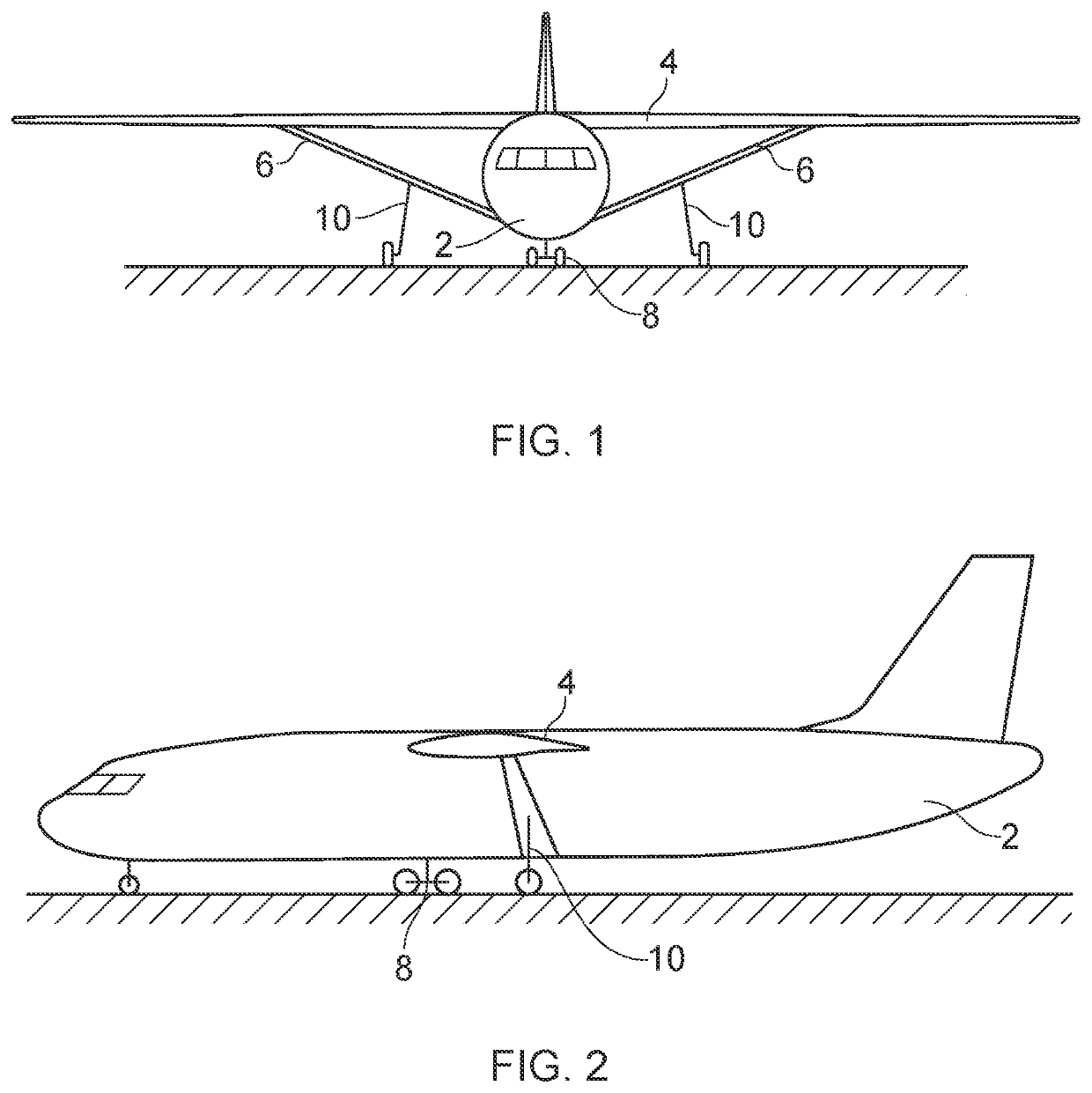
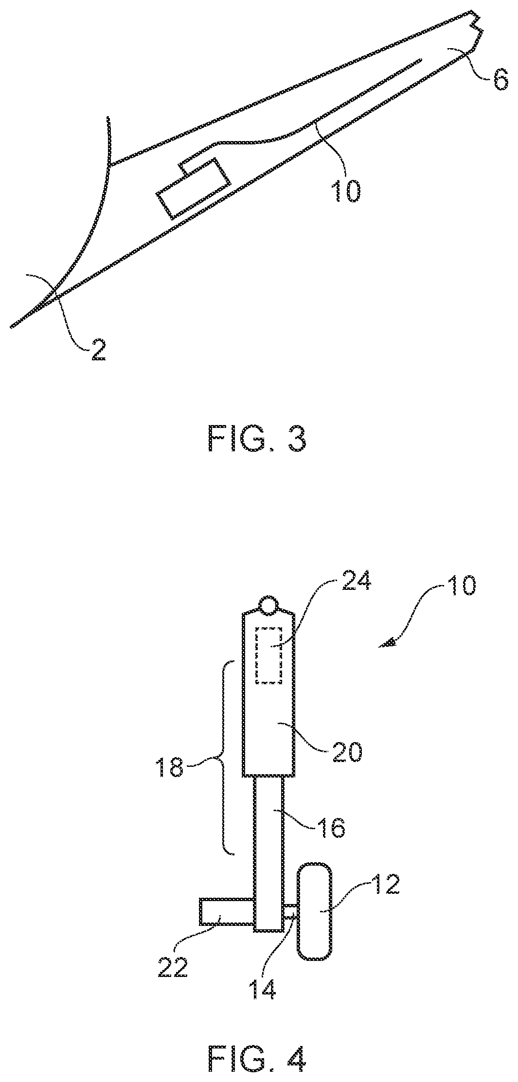
[0021]FIGS. 1 and 2 schematically illustrate an aircraft according to an embodiment of the present invention. The aircraft has a fuselage 2 of a generally tubular shape as is well known in the art and a pair of wings 4 connected to an upper portion of the fuselage. In this context the term ‘upper portion’ can mean any portion of the fuselage that is located higher (relative to the normal attitude of the aircraft in level flight or when on the ground) than the horizontal median plane of the fuselage. Connected between the underside of each wing 4 and a lower portion of the fuselage 2 is a respective wing support strut 6. In this context the term ‘lower portion’ can mean any portion of the fuselage that is located lower (relative to the normal attitude of the aircraft in level flight or when on the ground) than the portion of the fuselage to which the wing is connected. Each wing support strut 6 preferably has an aerofoil cross-section. A main landing gear 8 is mounted to the fuselage...


PUM


Abstract

An aircraft comprising a fuselage, a pair of wings connected to an upper portion of the fuselage, and a pair of wing support struts, each wing support strut being connected between a lower portion of the fuselage and an underside of the adjacent wing, wherein at least one centre landing gear assembly is connected to the fuselage and is configured to be retractable within the fuselage, and a respective outrigger landing gear is connected to each wing support strut, each outrigger landing gear being configured to be retractable within the respective wing support strut.

Description

BACKGROUND[0001]The vast majority of commercial airliners follow the same basic design of having the wings connected to the fuselage at or towards the bottom of the fuselage section with each wing housing at least one retractable main landing gear designed to fully retract into the wing. A central nose gear mounted towards the front of the fuselage completes the landing gear configuration in what is generally referred to as a tricycle arrangement. Examples of such aircraft include the Boeing 737 series and Airbus A320 series.[0002]However, there is an increasing interest in providing an airliner of comparable dimensions having a high mounted pair of wings, with each wing mounted substantially at the top of the fuselage. It is currently thought that such a design will bring improvements in reduced drag of the aircraft and therefore increase efficiency of operation. It is already known for some small passenger aeroplanes to have such high mounted wings, for example the British Aerospa...

Claims


Application Information

Patent Timeline
IPC IPC(8): B64C25/12B64C25/04
CPCB64C25/12B64C25/04B64C25/10B64C1/26B64C3/18
Inventor SIMONNEAUX, YANN
Owner MESSIER DOWTY
Why Eureka
Try Eureka