Expandable implants

a technology of expandable implants and implants, which is applied in the field of medical implants, can solve the problems of back problems, debilitating and debilitating, and achieve the effect of increasing the load and adding rigidity

Pending Publication Date: 2022-10-06
NUVASIVE
View PDF3 Cites 0 Cited by
  • Summary
  • Abstract
  • Description
  • Claims
  • Application Information

AI Technical Summary

Benefits of technology

[0009]In some embodiments, anti-migration features are provided to restrict undesired rotation of the lead screws. The anti-migration features provide added rigidity and increase an amount of load the expandable implant is configured to support.

Problems solved by technology

Back problems are one of the most common and debilitating occurrences in people of all ethnicities.
One of the causes of back pain and disability results from the rupture or degeneration of one or more intervertebral discs in the spine.

Method used


Image

  • Expandable implants
  • Expandable implants
  • Expandable implants

Examples


first embodiment

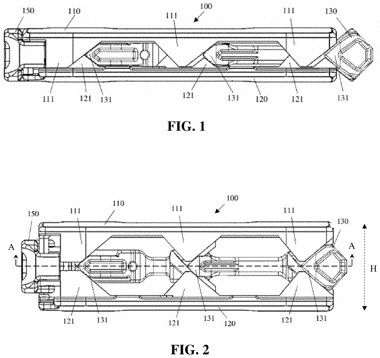
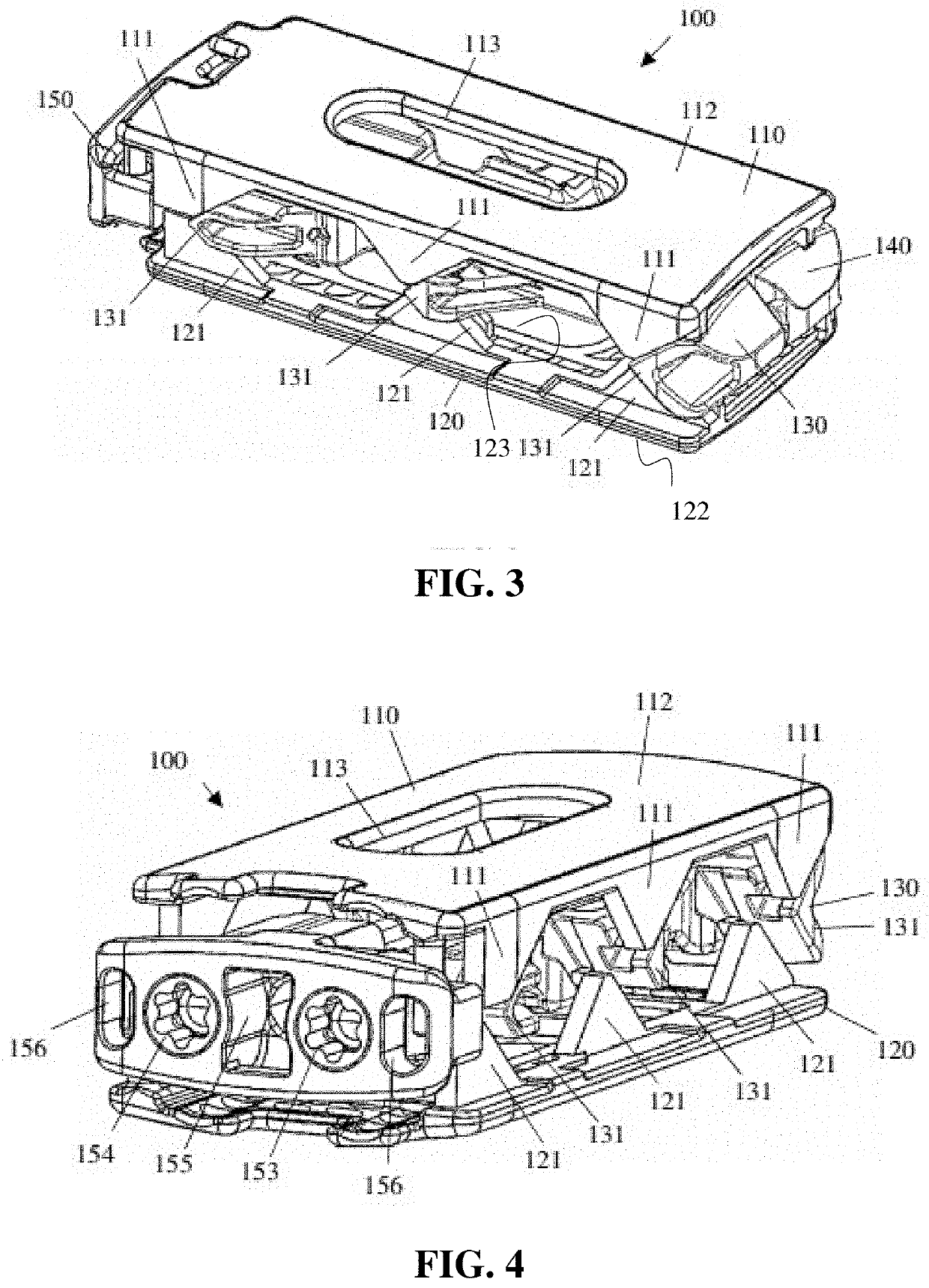
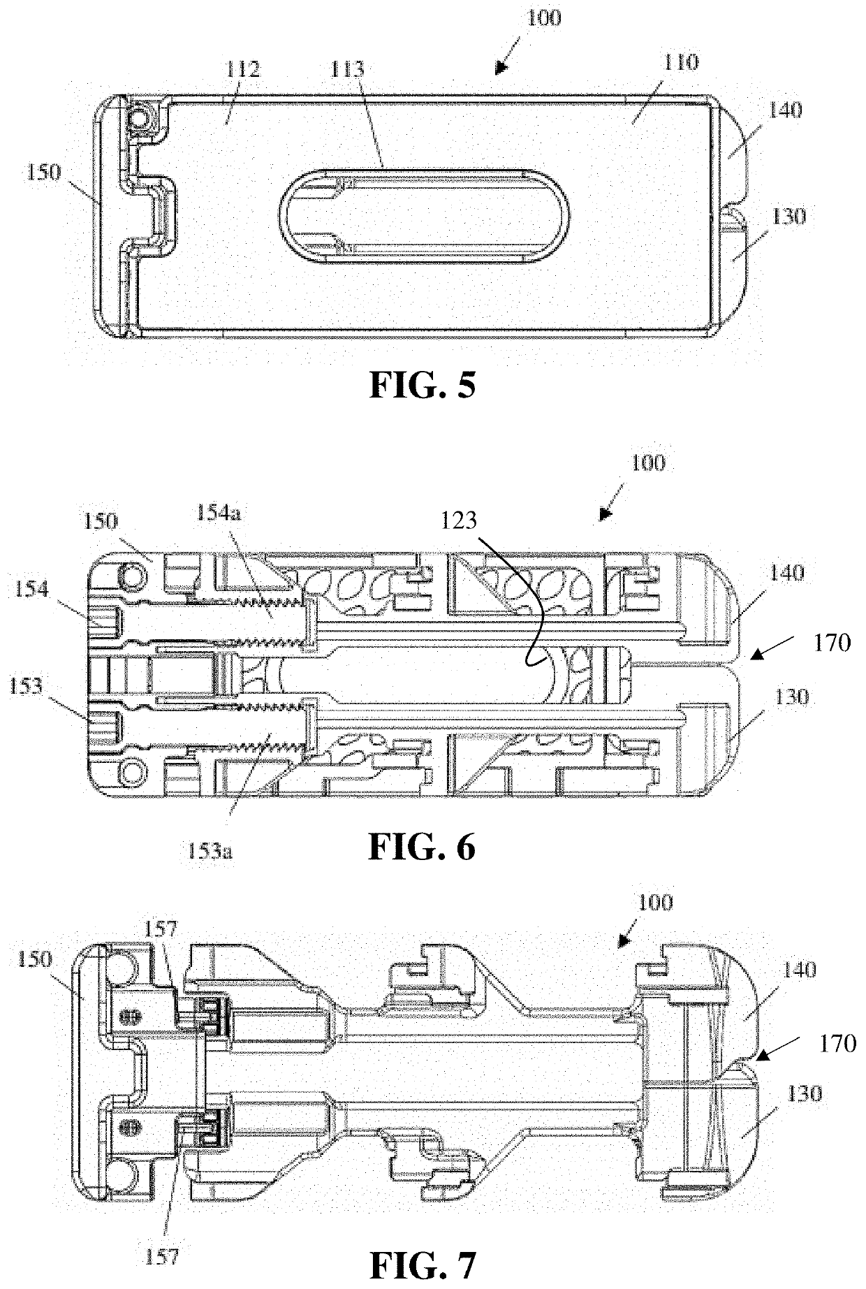
[0068]Now turning to the drawings, FIG. 1-13 show various views of an expandable implant 100 in accordance with a

[0069]FIG. 1 shows an expandable implant 100 collapsed in a first configuration. Expandable implant 100 is shown including a first endplate 110, a second endplate 120, a first translating member 130 (FIGS. 5-8) and a second actuator having a second translating member 140 (FIGS. 5-8). First translating member 130 may be configured to move independently from second translating member 140, and first translating member 130 and second translating member 140 may be configured to change a spatial relationship between first endplate 110 and second endplate 120.

[0070]The expandable implant 100 may be inserted through an access incision in a collapsed configuration to reduce an insertion profile of expandable implant 100. The first endplate 110 and the second endplate 120 further include a fusion aperture 113 (FIGS. 3-5), 123 (FIG. 3) and a bone contact surface 112 (FIGS. 3-5), 122...

second embodiment

[0096]FIGS. 17-20 show an expandable implant 200 including: a first endplate 210, a second endplate 220, a first translating member 230 disposed between first endplate 210 and second endplate 220 and moveably coupled to a first drive screw 253, and a second translating member 240 disposed between the first endplate 210 and second endplate 220 and moveably coupled to a second drive screw 254. First translating member 230 is configured to move independently from second translating member 240, and first translating member 230 and second translating member 240 are configured to change a spatial relationship between first endplate 210 and second endplate 220. First and second translating members 230, 240 are mirror images of each other, and therefore, have corresponding features.

[0097]In this embodiment, the first endplate 210 and the second endplate 220 include a porous bone contact surface 211, 221. The first endplate 210, the second endplate 220, and any other component of the expanda...

third embodiment

[0106]Some embodiments may include anti-rotation features to restrict undesired rotation of the lead screws. The anti-rotation features provide added rigidity and increase an amount of load the expandable implant is capable of supporting. For example, FIG. 21 and FIG. 22 show an actuator housing 350 of an expandable implant 300 in accordance with a third embodiment, the actuator housing 350 including an anti-rotation feature 357 configured to restrict an undesired rotation of the first drive screw 353 and the second drive screw 354. In this embodiment, the anti-rotation features 357 include a plurality of flexible members 357 extending from the actuator housing 350. The first drive screw 353 and the second drive screw 354 of this embodiment include a plurality of divots 353b, 354b, each configured to receive at least a portion of each of the plurality of flexible members 357 therein with the anti-rotation feature configured to ratchet and prevent undesired rotation of the drive scre...


PUM


Abstract

An expandable implant includes: a first endplate, a second endplate, a first translating member moveably coupled to a first actuator, and a second translating member moveably coupled to a second actuator. The first translating member may be configured to move independently from the second translating member, and the first translating member and the second translating member may be configured to change a spatial relationship between the first endplate and the second endplate. The change in spatial relationship may change a resulting height, length, width, angle of lordosis, or other dimension of the expandable implant.

Description

CROSS REFERENCE TO RELATED APPLICATIONS[0001]The present patent application claims priority to U.S. Provisional Patent Application No. 63 / 170,532, filed Apr. 4, 2021; U.S. Provisional Patent Application No. 63 / 170,570, filed Apr. 5, 2021; and U.S. Provisional Patent Application No. 63 / 249,129, filed Sep. 28, 2021.BACKGROUND OF THE INVENTIONField of the Invention[0002]The present disclosure relates generally to medical implants, and more particularly to expandable implants.Description of the Related Art[0003]Back problems are one of the most common and debilitating occurrences in people of all ethnicities. In the United States alone, over 500,000 spine lumbar and cervical fusion procedures are performed each year. One of the causes of back pain and disability results from the rupture or degeneration of one or more intervertebral discs in the spine.[0004]Surgical procedures are commonly performed to correct problems with displaced, damaged, or degenerated intervertebral discs due to t...

Claims


Application Information

Patent Timeline
Patent Type & Authority Applications(United States)
IPC IPC(8): A61F2/44
CPCA61F2/447A61F2002/30556A61F2/30749A61F2/4455A61F2002/30266A61F2002/30331A61F2002/30398A61F2002/30405A61F2002/30507A61F2002/30537A61F2002/30538A61F2002/30576A61F2002/30578A61F2002/3092A61F2002/3093A61B17/8042A61F2002/30484
Inventor BESAW, CHRISTOPHERSWEENEY, THOMASUYEKAWA, SCOTTMIKELS, GARRETTLILLIG, STEVEN
Owner NUVASIVE
Why Eureka
Try Eureka