Pallet rack with camber beams

a technology of camber beams and pallet racks, which is applied in the direction of movable shelf cabinets, furniture parts, dismountable cabinets, etc., can solve the problems of limiting increasing the manufacturing cost and weight of pallet racks, and increasing so as to increase the load carrying capacity of racks, increase the local carrying capacity of beams, and increase the amount of load weight

Inactive Publication Date: 2006-03-07
STEEL KING INDS
View PDF17 Cites 36 Cited by
  • Summary
  • Abstract
  • Description
  • Claims
  • Application Information

AI Technical Summary

Benefits of technology

[0003]The storage rack of the invention has elongated beams attached to upright columns with connectors. The beams have cambers or upward convex curvatures along the lengths thereof. The upward convex curvatures of the beams increases the local carrying capacity of the beams. In use, a portion of the weight of the load on the beams is taken up by the amount of weight required to overcome or flex the beams toward a linear straight shape. The upward cambers of the beams establishes additional useable deflection of the beams which increases the amount of load weight that can be supported on the beams to make the beams deflect to 1 / 180th of the spans of the beams below a horizontal plane. The load carrying capacity of the rack is increased without increasing size and weight of the beams and columns supporting the beams.

Problems solved by technology

This increases the manufacturing costs and weight of the pallet racks and shipping cost of columns and horizontal beams to the assembly locations.
Building and design codes limit the amount of load weight that can be supported by a horizontal beam of a pallet rack.

Method used


Image

  • Pallet rack with camber beams
  • Pallet rack with camber beams
  • Pallet rack with camber beams

Examples


Embodiment Construction

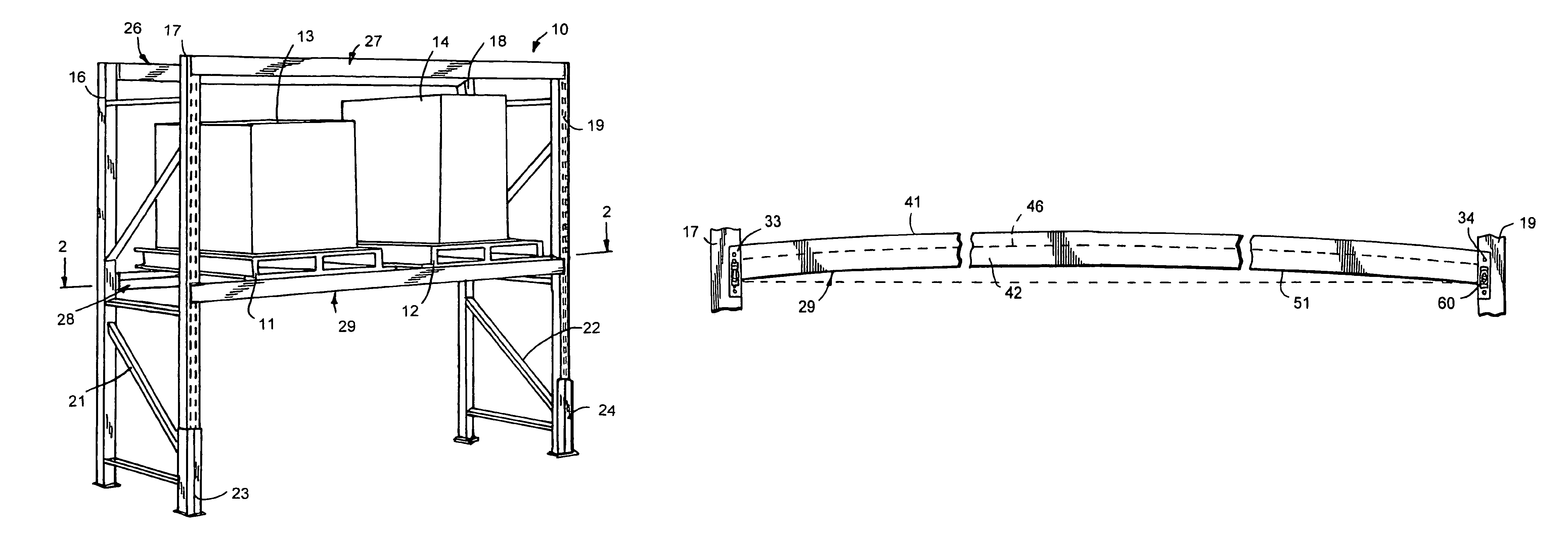
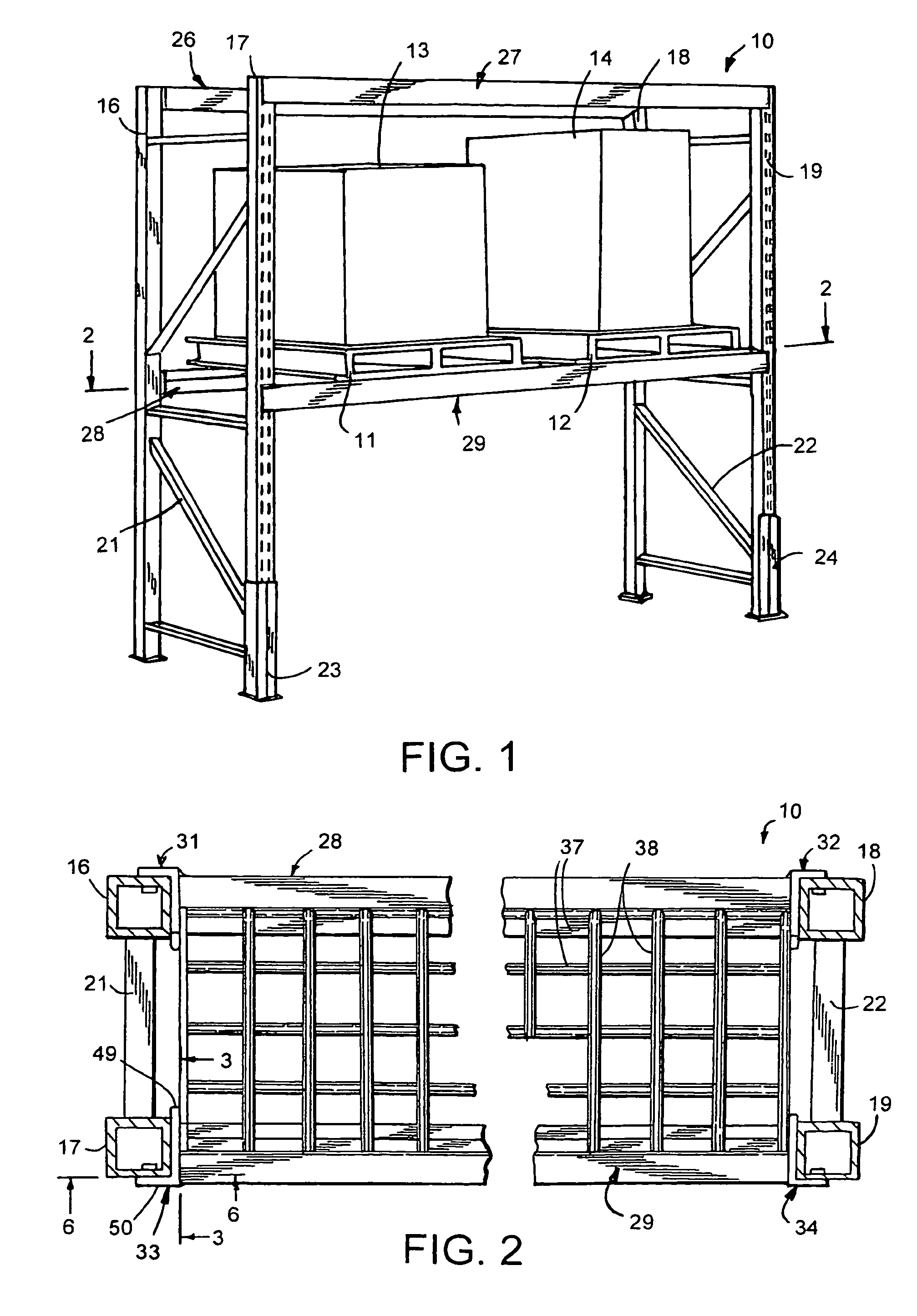
[0017]A storage rack 10, shown in FIG. 1, used in retail and warehouse environments for storing products and pallets 11 and 12 supporting containers or cartons containing products. Rack 10 has upright frames having columns or posts 16, 17, 18 and 19. Each column has vertical rows of keyhole slots. Columns 16–19 are tubular metal members having continuous weld construction which provides more torsional strength than roll formed U-shaped rack columns. The upright frames have cross members 21 extended between and secured with welds to columns 16 and 17. Cross members 22 extend between and are secured with welds to columns 18 and 19. The adjacent upright frames and columns 16, 17 and 18, 19 are identical in structure. Additional frames can be used to extend the length of the storage rack. The vertical length of columns 16–19 can vary to increase the number of rack shelves. The size of columns 16–19 can be changed to increase their structural strength. The columns can be upright channel ...


PUM


Abstract

A storage rack has upright columns supporting vertically cambered beams having step box or channel shapes accommodating a generally horizontal deck for carrying pallets and product loads. The beams have upward cambers or convex curvatures that increase the load carrying capacity of the rack.

Description

FIELD OF THE INVENTION[0001]The invention is in the art of storage racks for accommodating products and pallets for holding products and containers. The particular storage racks of the invention have upright columns and beams attached to the columns with boltless or bolted connectors.BACKGROUND OF THE INVENTION[0002]Pallet racks are in common use in product distribution centers, product and parts storerooms, and retail home center and food stores. The pallet racks have upright tubular or channel columns supporting straight horizontal beams. Cross beams and decks mounted on the horizontal beams are used to support pallet loads and products. The strength and rigidity of pallet racks have been increased by using closed tubular steel columns and tubular high strength steel horizontal beams. Additional pallet rack strength has been achieved by increasing the size and weight of the columns and horizontal beams. This increases the manufacturing costs and weight of the pallet racks and ship...

Claims


Application Information

Patent Timeline
Patent Type & Authority Patents(United States)
IPC IPC(8): A47F5/00A47B47/02A47B96/14A47F5/01B65G1/02
CPCA47F5/01B65G1/02A47B96/1441A47B47/027A47B47/021
Inventor ANDERSON, JAYCE S.ROSENBERG, GARY J.KRUEGER, STEVEN E.SNIFF, WILLIAM R.
Owner STEEL KING INDS
Why Eureka
Try Eureka