Transportation signaling device

a signaling device and transportation technology, applied in the field of transportation, can solve the problems of large power, inability to cast a light beam very far out into the waterway, severely limited information generated to passing ships and back from the buoy to maintenance personnel and monitoring entities, etc., to achieve rapid change of engine speed, increase load, and rapid change of propeller speed

Inactive Publication Date: 2004-03-25
RAST RODGER H
View PDF5 Cites 246 Cited by
  • Summary
  • Abstract
  • Description
  • Claims
  • Application Information

AI Technical Summary

Benefits of technology

0175] The present invention appreciates that "throttling" an engine to change speed is often a slow process, requiring estimates to be produced too far in advance. A speed control mechanism is described that provides a rapid means of changing engine speed while providing additional advantages.
0176] The present invention couples a variable load to the engines, such as a generator, the force required of the load can be varied rapidly in response to signals generated from the fluid flow estimates. Preferably one generator is coupled to each engine, or transmission, to allow independent variation of speed. The generators provide a source of redundant power generation, and a means for quickly varying propeller speed. It will be appreciated that changing the field current in a generator system increases the amount of load represented by the generator and it electrical power output.
0177] The current in the field winding controls the resistance that the generator places on the attached engine. Each generator is set for a specific baseline winding current that is varied in response to the estimations of screw load, so that the speed of each screw is modulated to be maintained at the desired speed without the periodic fluctuations and resultant vibrations. Therefore if a low load is estimated for the screw, then the winding current would be increased sufficiently to null (compensate) for the reduced load so that the screw would remain synchronized with the other screws.
0178] Therefore, calculations based on sensor data is used to alter the field currents to compensate for upcoming pressure transitions. The engines are therefore sped up or slowed down rapidly in sych with the oncoming known pressure changes whereby all engines stay synched with one another despite the pressure changes.

Problems solved by technology

Lighted buoys of this type, however, require large amounts of power and are unable to cast a light beam very far out into the waterway.
In addition, the amount of information generated to passing ships and back from the buoy to maintenance personnel and monitoring entities, is severely limited.

Method used


Image

  • Transportation signaling device
  • Transportation signaling device
  • Transportation signaling device

Examples


embodiment 10

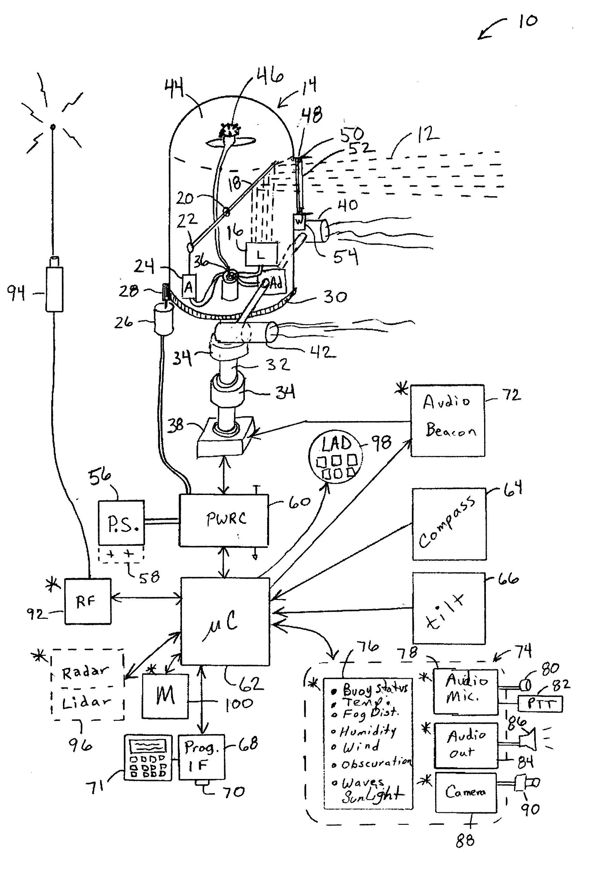
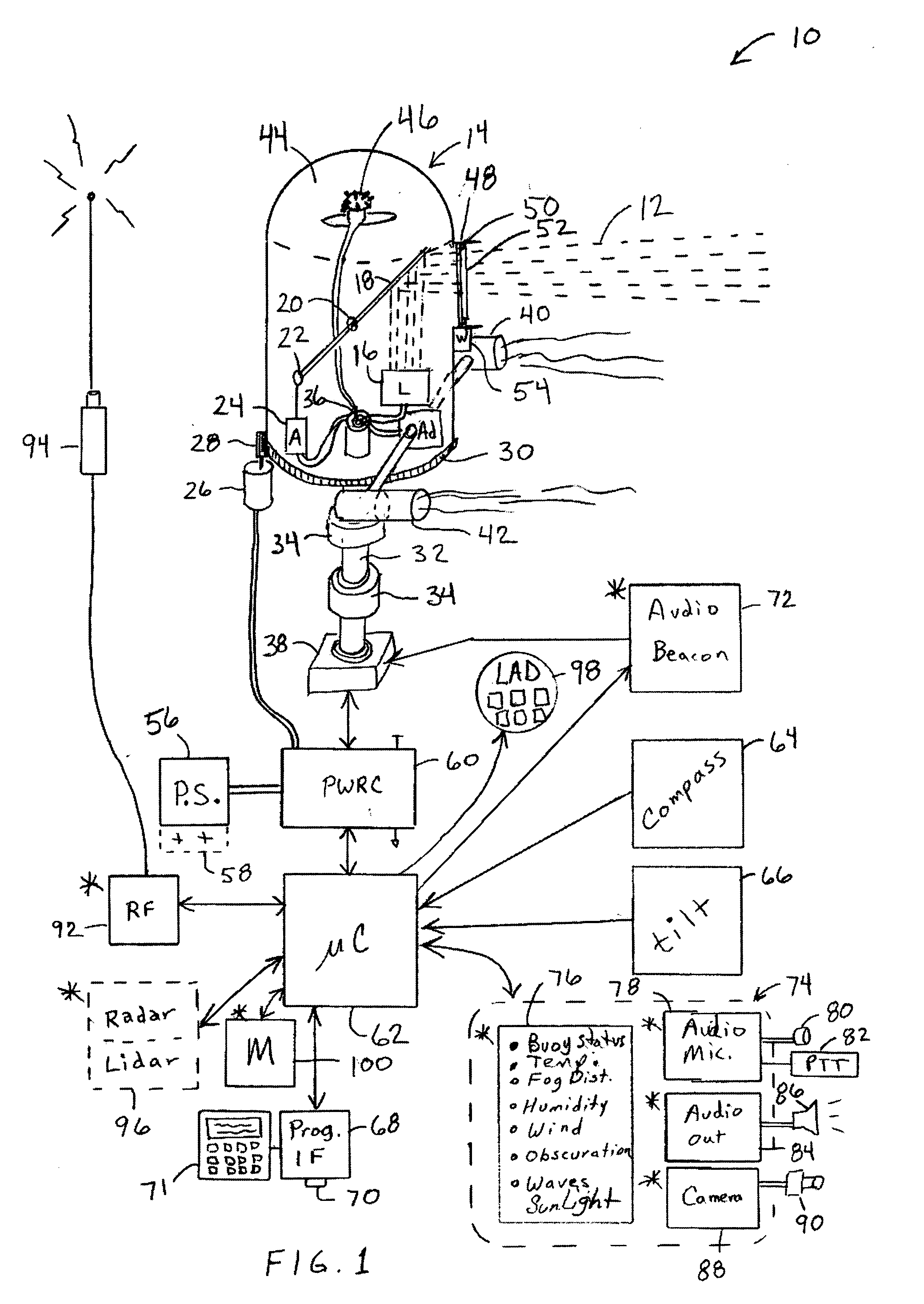
[0078] FIG. 1 depicts the invention with rotating light beacon 12 within a housing 14. The light beacon 12 is generated from a laser light source 16, preferably comprising a number of elements, such as from four to eight (4-8) which are retained in a given pattern, or angular spread. A means for directing the path of the laser light is provided, exemplified as a means for changing inclination angle of the light and a means for changing the horizontal direction of the light. It will be appreciated that light may be directed in two or three dimensions using a number of alternative mechanisms.

[0079] The means for changing inclination angle is exemplified as a mirror 18 connecting through pivot 20 and connected at distal end 22 to actuator 24. Movement of the actuator changes the mirror angle and thus the angular direction of the beam. The inclination adjustment preferably is capable of adjusting the inclination angle of the light over an angle that is equal to or approaches the angle b...

embodiment 1500

[0487] FIG. 38 illustrates a generalized embodiment 1500 of the invention, which can be reconfigured to fulfill the functions of any of the embodiments described above. Although the system may be implemented by one of ordinary skill according to the functional descriptions above, the schematic provides a basis from which these embodiments may be created.

[0488] Light test unit 1500 can be powered by a battery source 1502 or from a connection to the receptacle on the vehicle lighting system. A switching matrix 1506 is configured to allow the signals to be passed through directly, or interconnected under the control of microcontroller 1508. To perform more sophisticated testing the switching matrix 1506 is further configured for routing signals through a resistance for measuring current, connecting high impedance power between connections to detect shorts, and so forth depending on the application. Microcontroller 1508 preferably contains memory for storing sequences and parameters reg...

embodiment 1600

[0536] FIG. 39 depicts a preferred embodiment 1600 of the underside of a base 1601 containing sensing, positioning, and dispensement. A set of conventional lighting 1602 lights up an area of the pavement which is augmented by collimated (laser) lighting 1604 to aid in crack edge detection. A set of low resolution (inexpensive) cameras 1606 registers the locations of cracks and voids, preferably creating a three dimensional data set of both location and an estimated amount of material to be dispensed.

[0537] Two splash shields 1608 are shown to reduce the chances for the dispensed material to splatter or be carried by the wind to the crack / void detection sensors, exemplified by the optical elements.

[0538] A plurality of tracks 1610, 1612, 1614, 1616, 1618, are depicted upon which nozzles 1620 may be moved. Inclusion of a plurality of nozzles and tracks allows a number of complex cracks on a pavement surface to be simultaneously repaired. The use of two nozzles on the lateral tracks in...


PUM


Abstract

An apparatus for generating buoy light signals using a collimated light source. The system provides for communication of system conditions and ambient conditions, and can provide homeland security monitoring. The system senses motion of the buoy and compensates the direction of lighting, and optionally acoustics, being generated out over a body of water. Numerous other transportation related embodiments are described including devices for providing user comfort when flying, automotive signaling, auto parking control, sports bottles, visors, and lures.

Description

[0001] This application claims priority from U.S. provisional application serial No. 60 / 394,160 filed on Jul. 1, 2002.STATEMENT OF FEDERALLY SPONSORED RESEARCH OR DEVELOPMENT[0002] Not ApplicableREFERENCE TO A MICROFICHE APPENDIX[0003] Not Applicable[0004] 1. Field of the Invention[0005] This invention pertains generally to transportation and more particularly to a transportation signaling devices and other transportation related devices and systems.[0006] 2. Description of the Background Art[0007] Conventional maritime signaling devices (buoys) are configured with a light mounted atop a raised structure attached to a floating platform that is generally anchored to the floor of a body of water. These systems may additionally, or alternately, generate audio signals to warn ships and small boats of the presence of land. These buoys may be configured with a colored light, a sound, a color pattern marking, indicia, or combination thereof that provide identification of the buoy as a spec...

Claims


Application Information

Patent Timeline
Patent Type & Authority Applications(United States)
IPC IPC(8): B63B22/16B65D1/02B65D5/54
CPCB63B22/16B63B22/166B63B22/163
Inventor RAST, RODGER H.
Owner RAST RODGER H
Why Eureka
Try Eureka