
Tube-structured battery to be inserted into living body

Active Publication Date: 2013-01-31
IND ACADEMIC COOP FOUND GYEONGSANG NAT UNIV
View PDF6 Cites 24 Cited by
  • Summary
  • Abstract
  • Description
  • Claims
  • Application Information

AI Technical Summary

Benefits of technology

This patent describes a method of efficiently fixing an enzyme in a battery used to generate power in the body or blood vessels. The method also reduces toxicity and increases the battery's efficiency. Additionally, the patent discusses a method of initial driving a transformer circuit to boost the voltage generated by the battery and efficiently charge it. The overall effect of this patent is to provide a more powerful and efficient tube-structured battery for use in various medical applications.

Problems solved by technology

However, since the living body implantable medical devices have large sizes to give burdens to patients, many patients who have been implanted with the living implantable medical devices complain of inconveniences of wearing sensations.
However, since a volume of a primary battery occupying a considerable portion between about 20 v % and about 60 v % in these devices is great, remarkably reducing the sizes of the medical devices is limited.
This method causes a continuous charging, and the charging method using the terminal exposed to the outside causes inconveniences to patients.
Also, the charging method using the RF causes a safety problem.
In this case, a capacity of the battery is also reduced and thus cannot be used for a long time.
However, voltage and current densities generated from the electricity are very low, and thus it is impossible to apply the living body implantable biofuel battery as an enough power source to supply power to a living body implantable device.
Also, the exemplary embodiments are not required to overcome the disadvantages described above, and an exemplary embodiment may not overcome any of the problems described above.

Method used


Image

  • Tube-structured battery to be inserted into living body
  • Tube-structured battery to be inserted into living body
  • Tube-structured battery to be inserted into living body

Examples


second exemplary embodiment

[0275][Battery to be Inserted into Living Body According to Modified Exemplary Embodiment of Second Exemplary Embodiment]

[0276]FIG. 17 is a view illustrating a battery to be inserted into a living body according to a modified exemplary embodiment of the second exemplary embodiment of the present general inventive concept.

[0277]Referring to FIG. 17, a battery 1700 to be inserted into a living body includes a biofuel battery part 1710, a transformer circuit part 1720, and a secondary battery part 1730.

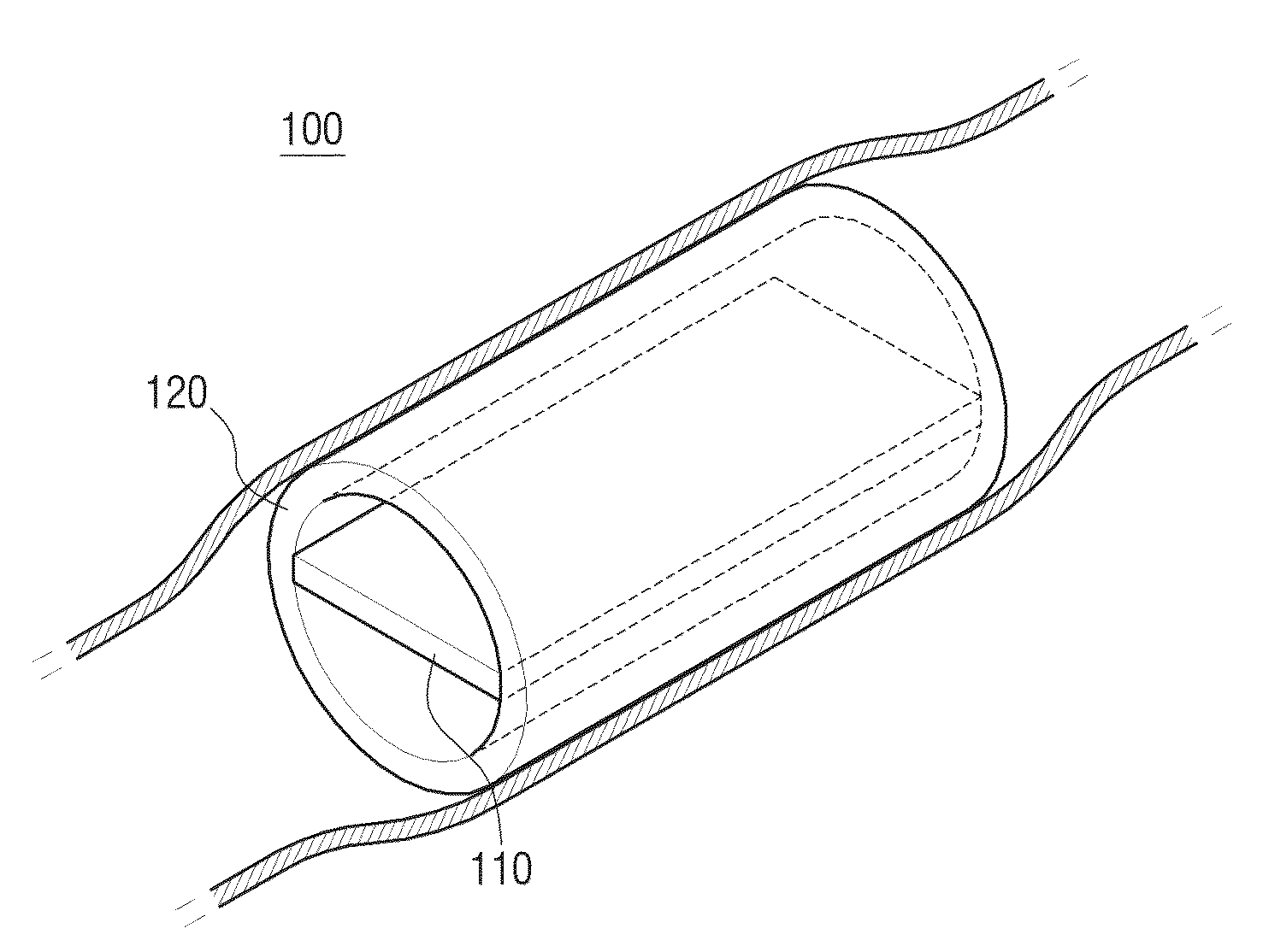
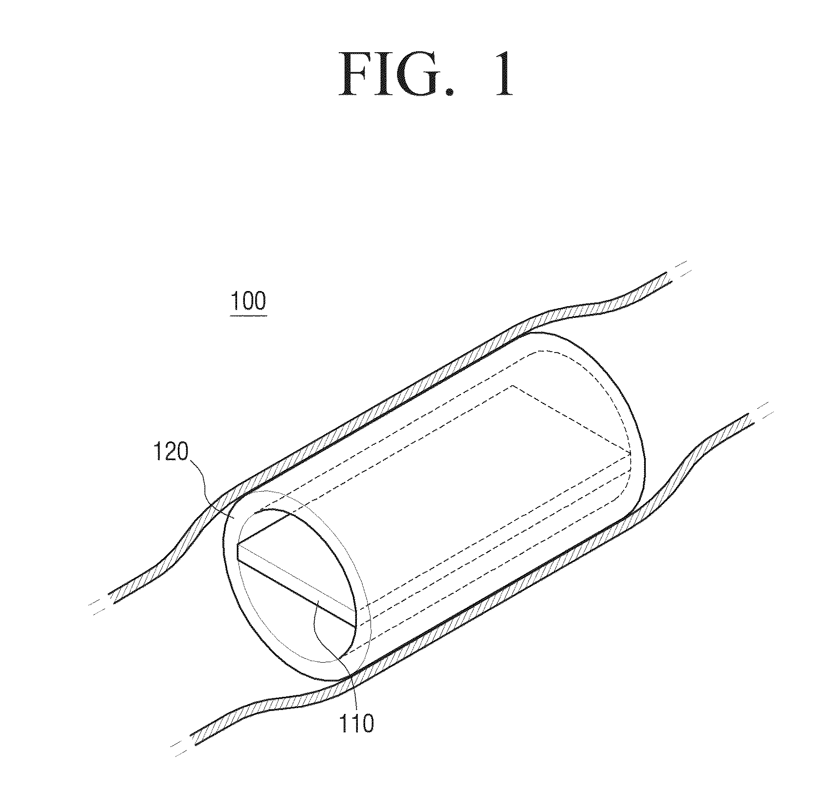
[0278]The biofuel battery part 1710 generates electric energy by using biofuel of the blood passing through an internal space having a tube structure whose both ends are opened.

[0279]The transformer circuit part 1720 adjusts a voltage or current density of the generated electric energy.

[0280]The secondary battery part 1730 is charged with the electric energy having the adjusted voltage or current density to store the electric energy.

[0281]The battery 1700 may further include a transrefle...

third exemplary embodiment

[0297][Battery to be Inserted in Living Body According to Modified Exemplary Embodiment of Third Exemplary Embodiment]

[0298]FIG. 19 is a view illustrating a battery to be inserted into a living body according to a modified exemplary embodiment of the third exemplary embodiment of the present general inventive concept.

[0299]Referring to FIG. 19, a battery 1900 to be inserted into a living body includes a fusion battery part 1910 and a support part 1920.

[0300]In the battery 1900, an inner cross-section of the support part 1920 may have a circular shape like an inner cross-section of the support part 1820 of FIG. 18. However, an outer cross-section of the support part 1920 may have a polygonal shape differently from an outer cross-section of the support part 1820 of FIG. 18. Therefore, the battery 1900 having a tube structure may have a polygonal pillar shape.

[0301]In this case, the fusion battery part 1920 may be inserted into (attached to) a side of the support part 1920 in a flat pl...

exemplary embodiment 1

[0463 of Fixing Enzyme

[0464](1) Reformation of CNT-Introduction of Carboxyl

[0465]MWCNT of 10 mg is put into an acid solution of 4 ml (sulfuric acid:nitric acid=3:1, volumetric ratio), gets ultrasonic waves for 3 hours in an ultrasonic cleaner, passes through a 0.2 μl filter, and is collected. This is cleaned with distilled water of 20 ml three times and then dried at a temperature of 60° C. to generate carboxyl.

[0466](2) Attaching of Linker Material

[0467]Distilled water of 20 ml is put into MWCNT collected in the step 1, and then ultrasonic waves are applied for 10 minutes in the ultrasonic cleaner in order to improve a dispersion degree. The MWCNT is agitated in a magnetic agitator, an MES buffer (pH=6.1) is added (final concentration, 50 mM), NHS is added (final concentration, 1 mg / mL), and EDC is added (final concentration, 1 mg / ml). The mixture is agitated for 30 minutes at a room temperature, passes through a 0.2 μm filter, and is cleaned with distilled water three times to obt...


PUM


Abstract

A tube-structured battery to be inserted into a living body is provided. The tube-structured battery includes: a biofuel battery part which generates electric energy by using biofuel in the blood passing through an internal space of the tube structure; a transformer circuit part which adjusts a voltage or current density by using the generated electric energy; and a secondary battery part which is charged with the electric energy by using the adjusted voltage or current density to store the electric energy, wherein the tube-structured battery is inserted into the living body or a blood vessel of the living body.

Description

BACKGROUND[0001]1. Field[0002]The present general inventive concept generally relates to a battery to be inserted into a living body, and more particularly, to a tube-structured battery to into a blood vessel of a living body.[0003]2. Description of the Related Art[0004]Living body implantable medical devices, such as an artificial heart, a pacemaker, a video pill, a diagnostic medical center, a drug infusion pump, etc., assist a patient to be diagnosed and cured. However, since the living body implantable medical devices have large sizes to give burdens to patients, many patients who have been implanted with the living implantable medical devices complain of inconveniences of wearing sensations.[0005]Therefore, many efforts to reduce the sizes of the living body implantable medical devices have been made. However, since a volume of a primary battery occupying a considerable portion between about 20 v % and about 60 v % in these devices is great, remarkably reducing the sizes of the...

Claims


Application Information

Patent Timeline
IPC IPC(8): H02J7/00H01M50/107
CPCA61N1/3785H01M2/0202Y02E60/527H01M8/16H01M2/022Y02E60/50Y02E60/10H01M50/107
Inventor KIM, KI-WONNAM, TAE-HYEONAHN, JOU-HYEONAHN, HYO-JUNCHO, GYU-BONGNOH, JUNG-PILKIM, CHANG-JOONZHANG, MEI-YUCHUNG, SE-KYOKANG, DONG-WOOCHO, KWON-KOORYU, HO-SUK
Owner IND ACADEMIC COOP FOUND GYEONGSANG NAT UNIV
Features
  • Generate Ideas
  • Intellectual Property
  • Life Sciences
  • Materials
  • Tech Scout
  • Unparalleled Data Quality
  • Higher Quality Content
  • 60% Fewer Hallucinations
Learn More