Vehicle, program and notification method

a technology for vehicles and drivers, applied in the field of vehicles, programs, and notification methods, can solve the problems of increased frequency of notification to drivers, increased actual speed exceeding the threshold value, and vehicle may reach a brake fade sta

Pending Publication Date: 2022-10-13
TOYOTA JIDOSHA KK
View PDF0 Cites 0 Cited by
  • Summary
  • Abstract
  • Description
  • Claims
  • Application Information

AI Technical Summary

Benefits of technology

[0006]An object of the present disclosure is to provide a technique capable of optimizing the frequency of notifications issued to the driver when the followability of the actual speed with respect to the target speed is lowered while the speed control by the autonomous driving system is being executed.
[0015]The first control mode is a control mode in which a relatively high target speed follow-up performance is realized through active use of the brake. Therefore, the speed error between the target speed and the actual speed is relatively unlikely to occur. According to the vehicle, the program, and the notification method according to the present disclosure, setting the threshold value to a relatively small value makes it possible to suppress the malfunction of the autonomous driving system from being overlooked. The second control mode is a control mode in which the target speed follow-up performance is relatively lowered than in the first control mode while the use of the brake is suppressed. Therefore, the speed error between the target speed and the actual speed is relatively likely to occur.
[0016]According to the vehicle, the program, and the notification method according to the present disclosure, setting the threshold value to a relatively large value makes it possible to suppress notifications that are not always necessary from being frequently issued. That is, according to the vehicle, the program, and the notification method according to the present disclosure, the frequency of notifications provided to the driver can be optimized when the followability of the actual speed with respect to the target speed is lowered while the speed control is being executed by the autonomous driving system.

Problems solved by technology

When a vehicle travels on a long downhill road, the vehicle may reach a brake fade state due to heavy use of a brake.
As a result, the occasion that the speed error between the target speed and the actual speed exceeds the threshold value increases, and the frequency of notifications to the driver also increases.
However, the increase in the speed error between the target speed and the actual speed in this case is temporary to suppress the brake fade.
Frequent notifications that are not always necessary can be annoying to the driver.
Therefore, the speed error between the target speed and the actual speed is relatively unlikely to occur.
Therefore, the speed error between the target speed and the actual speed is relatively likely to occur.

Method used


Image

  • Vehicle, program and notification method
  • Vehicle, program and notification method
  • Vehicle, program and notification method

Examples


first embodiment

1. First Embodiment

1-1. Vehicle Configuration Provided with Autonomous Driving System

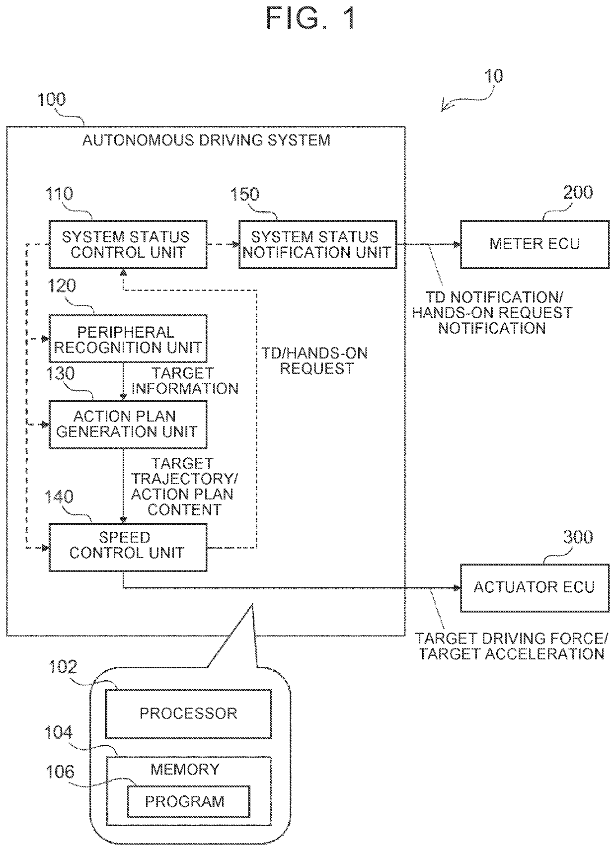
[0028]FIG. 1 is a block diagram showing a configuration of an autonomous driving system included in a vehicle according to a first embodiment of the present disclosure. An autonomous driving system 100 included in a vehicle 10 is an electronic control unit (ECU) provided with at least one processor 102 (hereinafter, simply referred to as a processor 102) and at least one memory 104 (hereinafter, simply referred to as a memory 104), that is, a computer. The memory 104 includes a main storage device and an auxiliary storage device. The memory 104 stores at least one program 106 (hereinafter, simply referred to as program 106) that can be executed by the processor 102 and various data related thereto. Various functions are realized in the autonomous driving system 100 as the processor 102 executes the program 106 stored in the memory 104. The ECU constituting the autonomous driving system 100 may be a ...

second embodiment

2. Second Embodiment

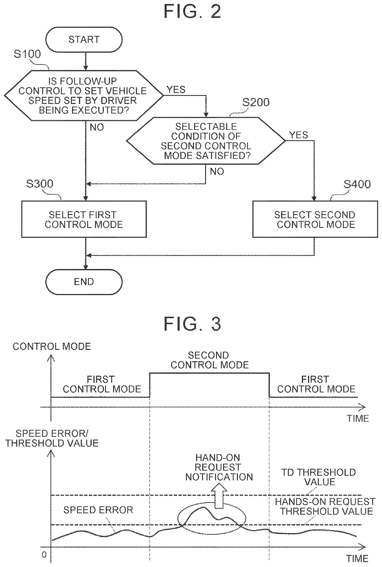
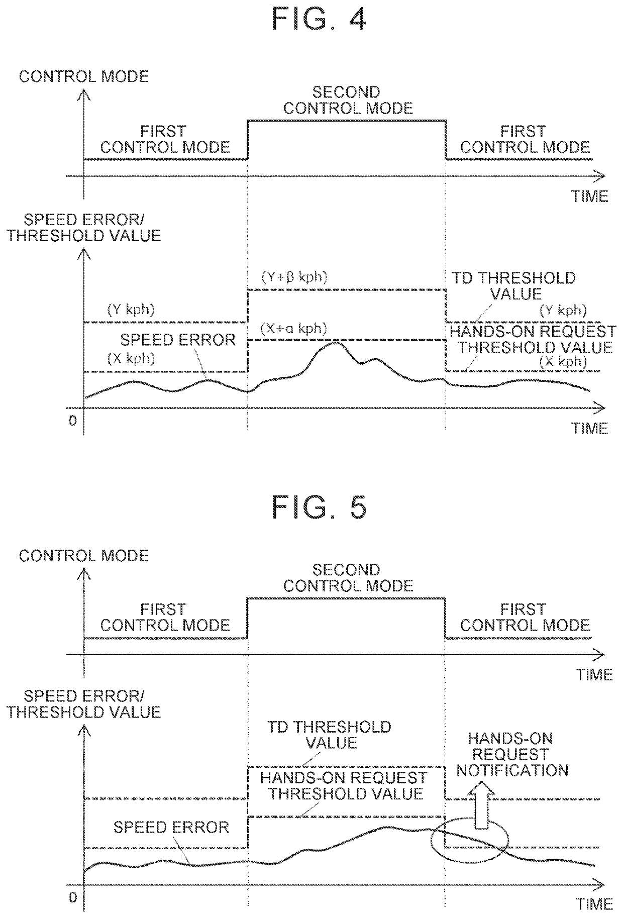
[0054]Next, a second embodiment according to the present disclosure will be described. However, the configuration of the autonomous driving system included in the vehicle according to the second embodiment is the same as that of the first embodiment, and is represented by the block diagram shown in FIG. 1. Further, in the second embodiment, the control mode of the speed control is determined in accordance with the flowchart in FIG. 2 that is common to the first embodiment. The second embodiment is different from the first embodiment in setting of the threshold value in each control mode.

[0055]FIGS. 5 and 6 each show an example of a time-dependent change in the speed error when the control mode is switched from the first control mode to the second control mode and then switched from the second control mode to the first control mode again. However, the time-dependent change in the speed error shown in FIG. 5 is the same as the time-dependent change in the speed err...

third embodiment

3. Third Embodiment

[0062]Next, a third embodiment according to the present disclosure will be described. However, the configuration of the autonomous driving system included in the vehicle according to the third embodiment is the same as that of the first embodiment, and is represented by the block diagram shown in FIG. 1. Further, in the third embodiment, the control mode of the speed control is determined in accordance with the flowchart in FIG. 2 that is common to the first embodiment. The third embodiment is different from the first embodiment and the second embodiment in setting of the threshold value in each control mode.

[0063]FIGS. 7 and 8 each show an example of a time-dependent change in the speed error when the control mode is switched from the first control mode to the second control mode and then switched from the second control mode to the first control mode again. However, the time-dependent change in the speed error shown in FIG. 7 is the same as the time-dependent ch...


PUM


Abstract

A control mode of speed control includes a first control mode in which an actual speed is caused to follow a target speed through active use of a brake and a second control mode in which the actual speed is caused to follow the target speed while use of the brake is suppressed. An autonomous driving system changes a threshold value to a value larger than a value in the first control mode when the control mode is switched from the first control mode to the second control mode, and changes the threshold value to a value smaller than a value in the second control mode when the control mode is switched from the second control mode to the first control mode.

Description

CROSS-REFERENCE TO RELATED APPLICATION[0001]This application claims priority to Japanese Patent Application No. 2021-066724 filed on Apr. 9, 2021, incorporated herein by reference in its entirety.BACKGROUND1. Technical Field[0002]The present disclosure relates to a vehicle, a program, and a notification method, and more particularly to a vehicle provided with an autonomous driving system that executes speed control for causing an actual speed to follow a target speed, and a suitable program and a notification method to be used for the vehicle.2. Description of Related Art[0003]When a vehicle travels on a long downhill road, the vehicle may reach a brake fade state due to heavy use of a brake. Japanese Unexamined Patent Application Publication No. 2005-028896 (JP 2005-028896 A) discloses that, leading to a situation where a braking force is required to be generated is suppressed by changing a control characteristics of follow-up traveling control to that having a smaller acceleration...

Claims


Application Information

Patent Timeline
Patent Type & Authority Applications(United States)
IPC IPC(8): B60W30/14B60W30/182B60W40/105B60W50/14B60W60/00B60W10/18
CPCB60W30/143B60W30/182B60W40/105B60W50/14B60W60/0053B60W10/18B60W2050/146B60W60/001B60W50/082B60W2720/10B60W2520/10
Inventor ASANO, TOMOTAKASHIZUHATA, HIROKIAOKI, YUTAKATAKAHASHI, SATOSHI
Owner TOYOTA JIDOSHA KK
Why Eureka
Try Eureka