
Apparatus and process for molding bottle preforms

a bottle preform and apparatus technology, applied in the field of molding bottle preforms, can solve the problems of insufficient expulsion of gas in the molding cavity, insufficient filling of the molding cavity, and inability to properly discharge air,

Pending Publication Date: 2022-10-27
SIPA SOCIETA INDUSTRIALIZZAZIONE PROGETTAZIONE E AUTOMAZIONE SPA
View PDF2 Cites 0 Cited by
  • Summary
  • Abstract
  • Description
  • Claims
  • Application Information

AI Technical Summary

Benefits of technology

The present invention aims to improve the ejection of gases from the molding cavity to reduce defects of the molded preforms. It also aims to reduce the obstruction of vent passageways to reduce the need for cleaning and maintenance. Finally, it aims to reduce defects at the neck of the preforms caused by the presence of vent passageways.

Problems solved by technology

However, often the gases in the molding cavity are not adequately expelled, in particular they are only partially expelled.
Therefore, disadvantageously, air is trapped and the molding cavity is not filled, and unacceptable defects may be generated on the preforms, such as, for example, burrs, burns and flow lines.
Such defects are more pronounced and occur more frequently as the injection speed increases.
Moreover, disadvantageously, the volatile compounds condensate on the surfaces delimiting the vent passageways, which tend to become obstructed.
At the state of the art, the cleaning operations require disassembling several components and they are not easy.
Another common defect of molded preforms is the presence of visible marks, generally in the form of lines, due to the presence of the vent passageways.
Such defects occur in particular at the preform neck and are due to the vent passageways, at the parting line, of the mold component which molds the outer surface of the preform neck.

Method used


Image

  • Apparatus and process for molding bottle preforms
  • Apparatus and process for molding bottle preforms
  • Apparatus and process for molding bottle preforms

Examples


Embodiment Construction

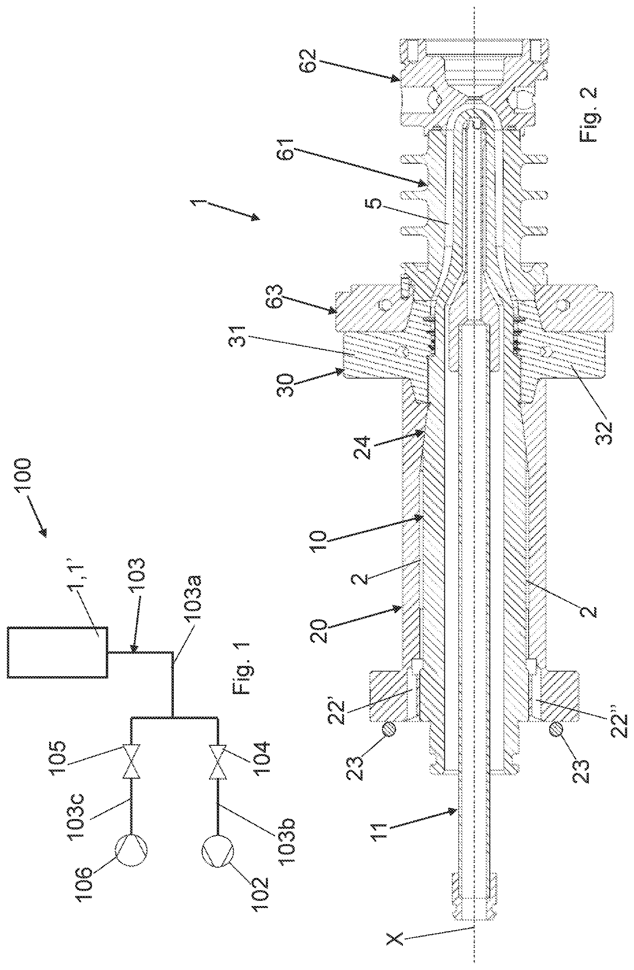
[0069]With reference to the Figures, embodiments of an apparatus 100, a device 1 and a process for molding one or more bottle preforms (not shown) are described. The preforms in particular are made by injecting molten plastic, or in other words, molten polymer, into a molding cavity 5. The preforms are made, for example of polyethylene terephthalate (PET).

[0070]In all the embodiments, the apparatus 100 comprises at least one molding device 1, also referred to as injection stack assembly.

[0071]The molding device 1 defines an axis X, preferably a longitudinal axis.

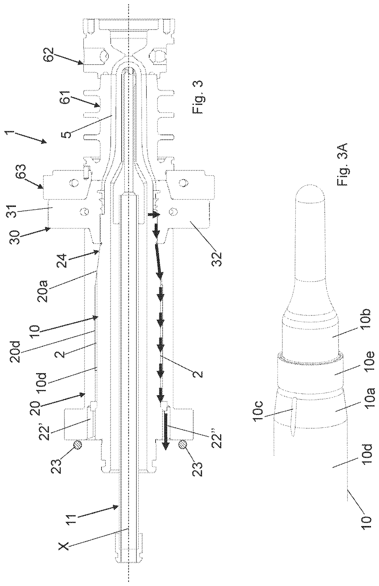
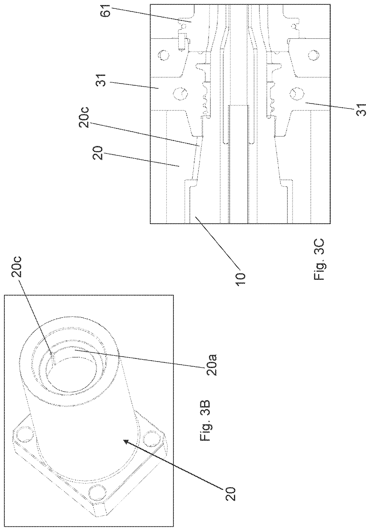
[0072]The molding device 1 is provided with at least one molding cavity 5 adapted to receive the molten plastic, and with at least one channel 2 for the air to pass from the at least one molding cavity 5 towards the outside of the molding device 1.

[0073]Said at least one channel 2 in particular is external to the molding cavity 5, in particular completely external to the molding cavity 5.

[0074]Apparatus 100 also comprises su...


PUM

PropertyMeasurementUnit
distanceaaaaaaaaaa
distanceaaaaaaaaaa
distanceaaaaaaaaaa

Abstract

A process for molding one or more bottle preforms, wherein molten plastic is injected into at least one molding cavity; and wherein air is drawn from the at least one molding cavity, through at least one channel for the air to pass from the at least one molding cavity towards the outside of the molding device, by means of suction means; and apparatus and device for performing such a process.

Description

CROSS-REFERENCE TO RELATED APPLICATIONS[0001]This application claims priority to PCT International Application No. PCT / IB2020 / 059206 filed on Oct. 1, 2020, which application claims priority to Italian Patent Application No. 102019000017675 filed on Oct. 1, 2019, the disclosures of which are expressly incorporated herein by reference.STATEMENT RE: FEDERALLY SPONSORED RESEARCH / DEVELOPMENT[0002]Not applicable.BACKGROUND OF THE INVENTIONField of the Invention[0003]The present invention relates to the field of molding plastic bottle preforms, in particular made of thermoplastic material, such as PET.[0004]The present invention in particular relates to an apparatus and a device for molding bottle preforms and a process for molding bottle preforms.Background Art[0005]The preforms of plastic bottles, in particular made of thermoplastic material, conventionally are manufactured by means of an injection molding or injection-compression molding process. In such processes, a given quantity of m...

Claims


Application Information

Patent Timeline
Patent Type & Authority Applications(United States)
IPC IPC(8): B29C45/17B29B11/08B29C45/34B29C45/26
CPCB29C45/1753B29B11/08B29C45/34B29C45/261B29C45/2602B29K2067/003B29K2105/258B29C45/43
Inventor CAVALET, ANDREASPINAZZE', PAOLOVESCOVO, FEDERICOZOPPAS, MATTEO
Owner SIPA SOCIETA INDUSTRIALIZZAZIONE PROGETTAZIONE E AUTOMAZIONE SPA
Learn More