
Removable left ventricular assist device with an aortic support apparatus

a technology of aortic support apparatus and assist device, which is applied in the direction of prosthesis, blood vessels, therapy, etc., can solve the problems of reduced cardiac output, troublesome problems arising from left ventricle disfunction, and many problems

Inactive Publication Date: 2001-05-08
NORTH TEXAS HEALTH SCIENCE CENTER AT FORT WORTH THE UNIVERSITY OF
View PDF13 Cites 20 Cited by
  • Summary
  • Abstract
  • Description
  • Claims
  • Application Information

AI Technical Summary

Benefits of technology

It is another object of the present invention to provide an apparatus and method for temporarily providing support to the inside aortic walls of a patient who is suffering from severe heart disease or trauma, such that the left ventricle is unable to maintain enough systemic arterial pressure to prevent the collapse of the walls of the aorta during use of an IABP.
Another object of the present invention is to expand the walls of the aorta during the ejection phase of the left ventricle, so as to enhance ejection of blood from the left ventricle into the aorta. This expansion of the aorta is synchronized with inflation of blocking balloons to prevent reflux of blood from arteries of the aortic arch and from the distal aorta and is also synchronized with deflation of a pumping balloon or blood flow control means positioned in the descending aorta.
It is another object of the present invention to provide an apparatus and method for blocking the flow of blood to the aortic arch arteries during left ventricle systole and concomitant deflation of the device's pumping balloon, so that backflow of oxygenated blood from the aortic arch and from the distal aorta will not reduce the efficiency of the pumping-function of the device.
It is another object of the present invention to provide a cost-effective and easily operated LVAD and aortic support and expansion capabilities that can be placed within the aorta of a patient by insertion through a femoral artery, as would be accomplished with a typical intra-aortic catheter.
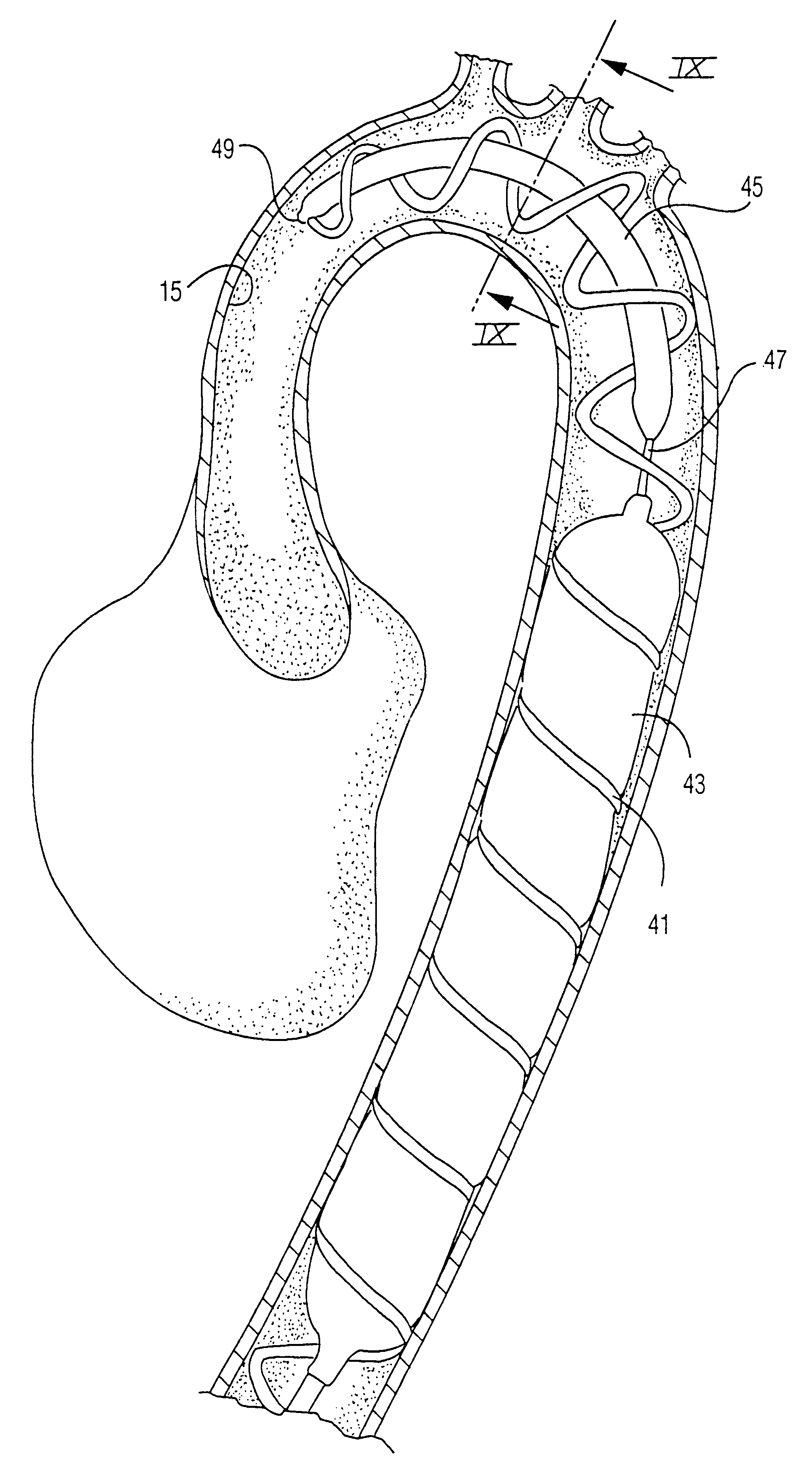
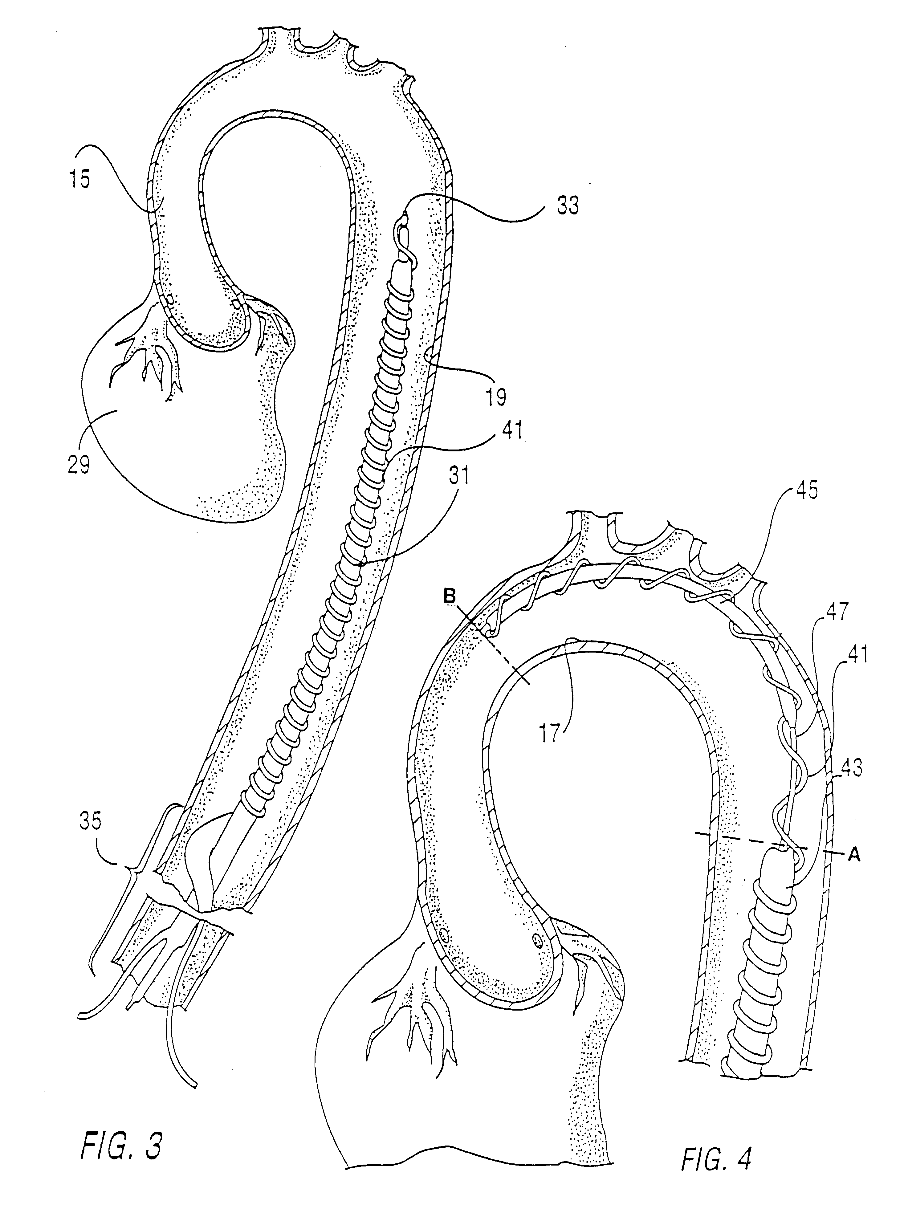
Two blocking balloons are also provided--the distal blocking balloon and proximal blocking balloon--having blocking positions when pressurized, and deflated positions when depressurized. The purpose of the distal blocking balloon is to block retrograde flow of blood coming from the descending aorta while the pumping balloon is in its sucking position. The distal blocking balloon functions by fitting against the inside wall of the descending aorta distal to the pumping balloon while in its blocking position. The distal blocking balloon is in the blocking position when the pumping balloon is in the sucking position. The distal blocking balloon is in a deflated position when the pumping balloon is in the pumping position, thus allowing blood to flow past the deflated balloon into the descending aorta and throughout the patient.

Problems solved by technology

Heart failure, especially resulting from disease or damage to the left ventricle of the heart, can result in many problems.
Problems arising from left ventricle disfunction are particularly troublesome since the heart itself, as well as the rest of the body, depends on left ventricle function for oxygenated blood to maintain aerobic respiration.
Heart failure results in ineffective emptying of the failing left ventricle during systole, which can result in (1) decreased cardiac output; and (2) elevated left atrial and pulmonary venous pressures, which cause pulmonary congestion and edema.
Pulmonary congestion and edema, or tissue swelling, prevent effective oxygenation of the arterial blood, and coupled with reduced cardiac output, and can lead to tissue hypoxia.
In the final stage of congestive heart failure, a vicious cycle leads to progressive systemic hypotension (low blood pressure), hypoxemia (oxygen depletion), tissue anoxia, further depression of cardiac function and cardiac arrhythmias, and ultimately, death.
However, the application of present IABP devices is limited to less severecases, since the IABP can function effectively only if the left ventricle is able to eject an adequate output to maintain a mean systemic arterial pressure greater than 60 mmHg.
This greatly limits the practical use of present IABPs.
But these devices are permanently placed within smaller arteries, and are not designed to be used in conjunction with other devices placed within the artery that assist in increasing systemic arterial blood pressure.

Method used


Image

  • Removable left ventricular assist device with an aortic support apparatus
  • Removable left ventricular assist device with an aortic support apparatus
  • Removable left ventricular assist device with an aortic support apparatus

Examples


Embodiment Construction

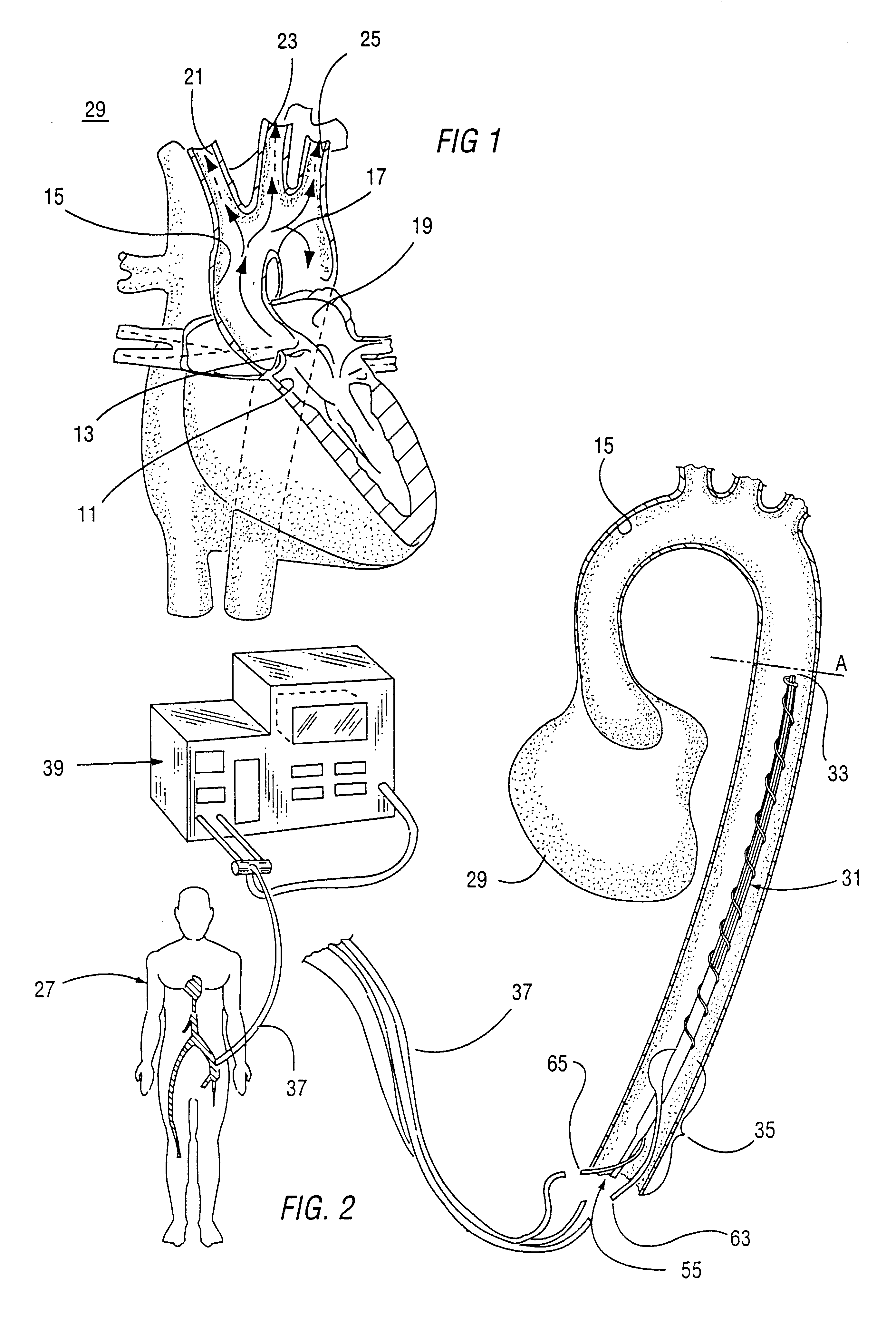
The present invention provides a dual function. The first is to provide a removable, pressurizable means of support and expansion of the inside walls of the aorta, in particular the aortic arch and descending portions of the aorta. In conjunction with this function, the present invention provides a LVAD using a blood flow control means that can be placed within the aorta simultaneous to and in conjunction with having the support means within the aorta. It is these two functions of the invention that allow its use in the aorta of a patient whose heart condition is such that presently available IABP devices are useless. The dual purpose of the present invention is shown in the preferred embodiment described below.

A partial cutaway view of the human heart 29 is shown in FIG. 1. The left ventricle 11 is where oxygenated blood coming from the lungs is pumped into the body. The aortic valve 13 controls the flow of blood, opening during the systole phase of the heart's cycle and closing du...


PUM


Abstract

An apparatus and method of temporarily replacing the function of the left ventricle in a patient whose heart is severely injured and is unable to maintain a systemic arterial pressure adequate to support the inside walls of patient's aorta, the method comprising a removable pressurizable support means having an external profile which is expandable to fit firmly against the inside wall of the aorta of a patient, wherein the external profile of the pressurizable support means presents a central opening that allows blood to flow through the aorta. The pressurizable support means can both support and expand the aorta under low blood pressure to assist the drawing of blood from the left ventricle. The central opening also allows for the placement of a blood flow control means. The blood flow control means can comprise a pumping balloon and a proximal blocking balloon, the two members pressurized and depressurized in opposition within the aorta of a patient to simulate systole and diastole of a healthy heart. The pumping balloon has a pressurized pumping position that is engaged while the proximal blocking balloon is in a depressurized deflated position.

Description

1. Field of the InventionThe present invention relates in general to a left ventricular assist device, and in particular to an apparatus and method for supporting the blood circulation when the heart is severely injured and is unable to maintain a systemic arterial pressure adequate to support the inside walls of patient's aorta. Still more particularly, the present invention relates to an apparatus and method for supporting and expanding the walls of the aorta from collapse during operation of the device, which might otherwise occur due to extremely low blood pressure and for providing diastole / systole-like cardiac function in a patient with a severely diseased or injured heart.2. Description of the Prior ArtIn the United States alone, 60,340,000 people have cardiovascular disease. Of these, over 2,000,000 have congestive heart failure, with more than 500,000 new cases diagnosed each year. In 1995, only 2,359 patients received heart transplants, the most permanent of treatments to ...

Claims


Application Information

Patent Timeline
Patent Type & Authority Patents(United States)
IPC IPC(8): A61M1/10A61F2/06A61F2/88A61M60/13A61M60/295A61M60/531A61M60/841A61M60/843A61M60/886
CPCA61M1/1072A61M1/1075A61F2/88A61M60/898A61M60/274A61M60/886A61M60/13A61M60/531A61M60/841A61M60/295A61M60/843
Inventor DOWNEY, H. FREDBIAN, XIAOMING
Owner NORTH TEXAS HEALTH SCIENCE CENTER AT FORT WORTH THE UNIVERSITY OF
Learn More